
Heat exchanger and water chilling unit with same

A heat exchanger and heat exchange zone technology, applied in refrigerators, refrigeration components, evaporators/condensers, etc., can solve the problems of increased compressor discharge resistance, high cleanliness requirements, complex manufacturing and installation, etc. Achieve the effect of reducing exhaust resistance, reducing processing steps, and convenient manufacturing and installation

Active Publication Date: 2017-11-21
CHONGQING MIDEA GENERAL REFRIGERATING EQUIP +1
View PDF9 Cites 1 Cited by
  • Summary
  • Abstract
  • Description
  • Claims
  • Application Information

AI Technical Summary

Problems solved by technology

[0002] Oil separators mainly include: compressor with built-in oil separator, external oil separator and centrifugal oil separator. The oil separator is a pressure vessel, limited by the design pressure and material, the pressure loss is often large, resulting in an increase in the exhaust resistance of the compressor and a corresponding decrease in the energy efficiency of the unit
[0003] The built-in oil separator placed in the heat exchanger in the related art has many processing procedures, is greatly affected by tooling, and requires high cleanliness

Method used


Image

  • Heat exchanger and water chilling unit with same
  • Heat exchanger and water chilling unit with same
  • Heat exchanger and water chilling unit with same

Examples


Embodiment Construction

[0030] Embodiments of the invention are described in detail below, examples of which are illustrated in the accompanying drawings. The embodiments described below by referring to the figures are exemplary and are intended to explain the present invention and should not be construed as limiting the present invention.

[0031] The following disclosure provides many different embodiments or examples for implementing different structures of the present invention. To simplify the disclosure of the present invention, components and arrangements of specific examples are described below. Of course, they are only examples and are not intended to limit the invention. Furthermore, the present invention may repeat reference numerals and / or letters in different instances. This repetition is for the purpose of simplicity and clarity and does not in itself indicate a relationship between the various embodiments and / or arrangements discussed. In addition, various specific process and mater...


PUM


Abstract

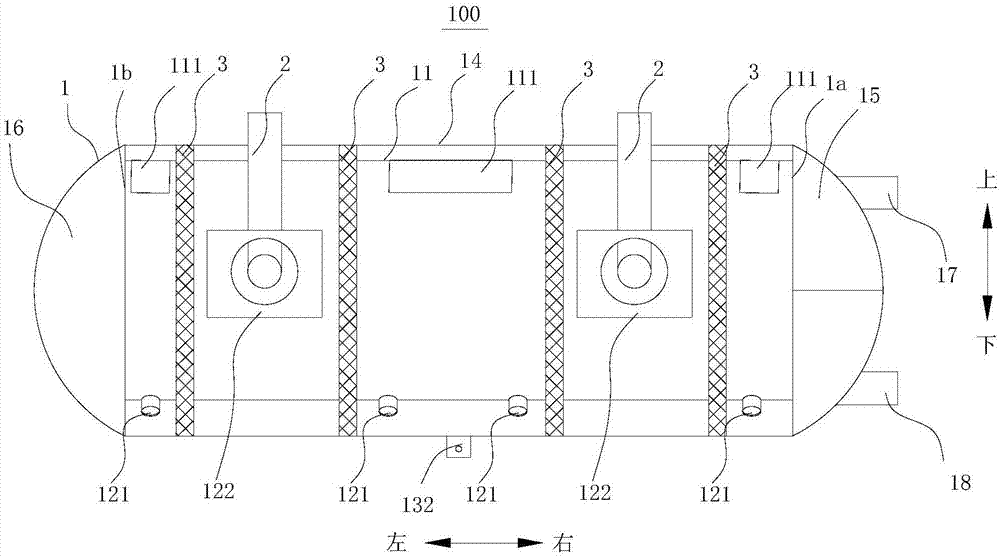
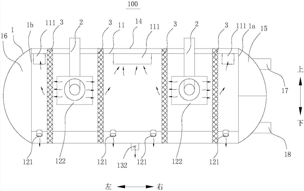
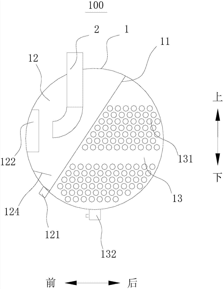
The invention discloses a heat exchanger and a water chilling unit with the same. The heat exchanger comprises a shell, gas inlet pipes and oil-gas separating pieces, wherein the shell is internally provided with a separating board, which divides the shell into a heat exchanging area and an oil separating area which are separated from each other; the oil separating area and the heat exchanging area are communicated through communicating channels; oil outlets are formed in the bottom of the oil separating area, a plurality of heat exchanging tubes are arranged in the heat exchanging area, and a liquid discharging hole is formed in the bottom of the heat exchanging area; one ends of the gas inlet pipes stretch into the oil separating area and extend toward the side wall of the oil separating area; the oil-gas separating pieces are arranged in the oil separating area, and are used for carrying out oil-gas separation on an oil-gas mixture which strikes the side wall. According to the heat exchanger provided by the invention, the manufacturing procedures of an oil separator are reduced on the basis of realizing the oil-gas separation, the influence of a tool to the oil separator is avoided, the requirement to cleanliness is reduced and the structure of the heat exchanger is compact.

Description

technical field [0001] The invention relates to the field of refrigeration, in particular to a heat exchanger and a chiller with the same. Background technique [0002] Oil separators mainly include: compressor with built-in oil separator, external oil separator and centrifugal oil separator. The oil separator is a pressure vessel, limited by the design pressure and material, the pressure loss is often large, resulting in an increase in the exhaust resistance of the compressor and a corresponding decrease in the energy efficiency of the unit. [0003] The built-in oil separator placed in the heat exchanger in the related art has many processing procedures, is greatly affected by tooling, and requires high cleanliness. Contents of the invention [0004] The present invention aims to solve one of the technical problems in the related art at least to a certain extent. For this reason, the present invention proposes a heat exchanger, which can reduce the processing steps of ...

Claims


Application Information

Patent Timeline
IPC IPC(8): F25B43/02F25B43/00F25B39/04F28B1/02
CPCF25B39/04F25B43/003F25B43/02F25B2339/04F25B2400/23F28B1/02
Inventor 顾同先
Owner CHONGQING MIDEA GENERAL REFRIGERATING EQUIP
Learn More