
System and method for digital holographic imaging

A technology of digital holography and imaging system, which is applied in the direction of instruments, etc., to achieve the effect of simple system, avoiding noise and error, and realizing real-time observation

Active Publication Date: 2017-11-21
SHENZHEN GRADUATE SCHOOL TSINGHUA UNIV
View PDF3 Cites 9 Cited by
  • Summary
  • Abstract
  • Description
  • Claims
  • Application Information

AI Technical Summary

Problems solved by technology

[0006] In order to solve the above technical problems, the present invention proposes a digital holographic imaging system and method, which can realize real-time observation of dynamic processes without increasing the complexity of the experimental system

Method used


Image

  • System and method for digital holographic imaging
  • System and method for digital holographic imaging
  • System and method for digital holographic imaging

Examples


Embodiment Construction

[0027] The present invention will be further described below with reference to the accompanying drawings and in combination with preferred embodiments.

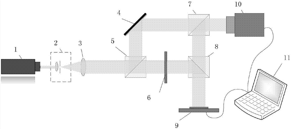
[0028] Such as figure 1 As shown, a schematic diagram of a digital holographic imaging system in a preferred embodiment of the present invention, wherein the digital holographic imaging system is used for holographic imaging of the sample 6 to be tested, including a laser 1, a spatial filter 2, a convex lens 3, a mirror 4, a first Beam cube 5 , second beam split cube 7 , third beam split cube 8 , spatial light modulator 9 , image sensor 10 and computer 11 .

[0029] The light emitted by the laser 1 is collimated by the spatial filter 2 and the convex lens 3 in turn to become a parallel beam (where the spatial filter 2 and the convex lens 3 form a beam expander and collimation unit), and the parallel beam is divided into two by the first beam splitting cube 5. After being reflected by the mirror 4, one beam passes through the...


PUM


Abstract

The invention discloses a system for digital holographic imaging. Light emitted by a laser is collimated to a parallel beam through a beam expanding collimation unit. The parallel beam is divided into two beams. One beam is reflected by a reflector, and forms reference light through a second beam splitter. The other beam passes through a to-be-tested sample, and is reflected to a spatial light modulator to be modulated by a third beam splitter, and then a modulated light beam passes through the third beam splitter and is reflected by a second beam splitter, and then object light is formed. Interference occurs on the surface of an image sensor by the reference light and the object light, and a hologram is generated. The image sensor and the spatial light modulator respectively connect with a computer. The spatial light modulator loads a plurality of different sampling matrixes in sequence in exposure time of the hologram. Each sampling matrix is respectively used to modulate object light in each sampling time period. The invention also discloses a digital holographic imaging method. The system and the method for digital holographic imaging can realize real-time observation of a dynamic process under the condition of not increasing complexity level of an experimental system.

Description

technical field [0001] The invention relates to the technical field of optical information processing and fast imaging, in particular to a digital holographic imaging system and method. Background technique [0002] Optical imaging is a very common phenomenon, and with the development of science and technology, optical imaging technology has penetrated into every aspect of our lives and is inseparable from our lives. Optical imaging is widely used in biological and medical research. Researchers can analyze the state and characteristics of organisms or cells through the acquired images, and even analyze the mechanism of drug action. [0003] According to different imaging characteristics, optical imaging can be divided into many types, and digital holography is a typical optical imaging technology. Holography was invented by British physicist Gabor in 1947. It uses the interference of light to record three-dimensional objects, and uses the principle of diffraction to reprodu...

Claims


Application Information

Patent Timeline
Patent Type & Authority Applications(China)
IPC IPC(8): G03H1/04G03H1/12G03H1/16
Inventor 苏萍陈虎马建设
Owner SHENZHEN GRADUATE SCHOOL TSINGHUA UNIV
Learn More