A Narrow Slot UWB Antenna
An ultra-wideband antenna and slot technology, applied in the field of narrow-slot ultra-wideband antennas, can solve the problem of unstable antenna pattern, and achieve the effect of simple structure, narrow gap and easy integration
- Summary
- Abstract
- Description
- Claims
- Application Information
AI Technical Summary
Problems solved by technology
Method used
Image
Examples
Embodiment 1
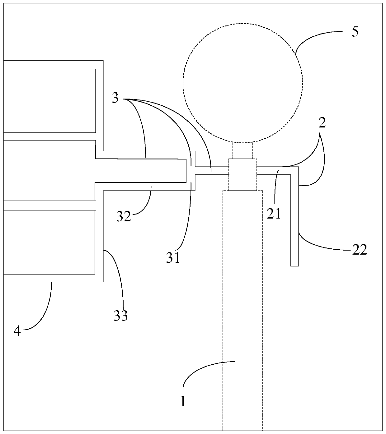
[0038] like figure 1 As shown, a narrow-slot ultra-wideband antenna includes a microstrip line 1, a slot line 2, a slot-line coplanar waveguide conversion structure and a terminal opening radiation slot unit.
[0039] In this embodiment, the antenna is printed on a single-sided copper-clad 0.8mm thick FR-4 dielectric board, the slot line 2 is opened on the metal surface of the dielectric board, and the microstrip line 1 is printed on the dielectric board. On the non-metallic surface, the non-metallic surface is on the back of the metal surface. That is, in this embodiment, a slot is made on the metal surface side of the dielectric plate, and the designed microstrip line 1 is printed on the non-metal surface side to feed the slot. In this embodiment, the dielectric plate used for the antenna is a 0.8 mm thick FR-4 substrate, which is only used for supporting the metal plate and facilitating printing. In other embodiments, the antenna structure can also be used on other substra...
Embodiment 2
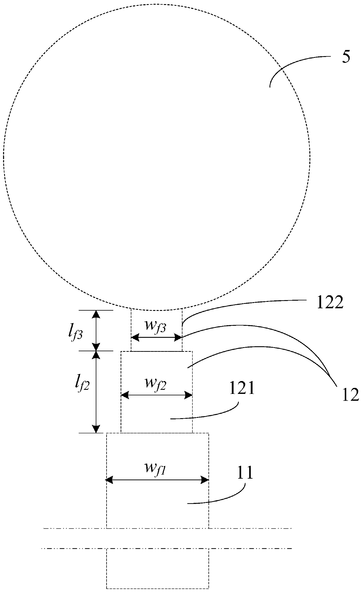
[0056] On the basis of Embodiment 1, the microstrip line 1 and the slot line 2 are further improved in this embodiment:
[0057] like figure 2 As shown in the figure, the end of the microstrip line 1 is in a stepped structure, and the width of the stepped structure decreases in turn along the direction from the front end to the end of the microstrip line 1 (that is, from the bottom at least), and the end of the microstrip line 1 A circular patch 5 is also attached. Specifically, the microstrip line 1 includes a microstrip line body 11 and a transition line 12. The transition line 12 includes a first transition line 121, a second transition line 122, a circular patch 5, a second transition line 122, The first transition line 121 and the main body 11 of the microstrip line are connected in sequence, and the widths of the second transition line 122 , the first transition line 121 , and the main body 11 of the microstrip line increase in sequence.
[0058] The slot line 2 is an...
Embodiment 3
[0070] The only difference between this embodiment and Embodiment 1 or Embodiment 2 is that the antenna structure in this embodiment is used on a metal surface without a substrate, that is, all the slots of the antenna are opened on the metal surface of the metal plate without a substrate, wherein , the slot line 2 is opened on the metal surface of the metal plate, and the microstrip line 1 is suspended on the back of the metal surface with the slit and does not contact the metal plate, that is, the microstrip line 2 becomes a suspended metal strip, and the position is not change without changing the electric field mode distribution of the feeder.
[0071] Since the substrate is only used for supporting the metal plate and facilitating printing, the substrate is not used in this embodiment. The rest of the structures are completely the same as in Example 1 or Example 2.
PUM
 Abstract
Description
Claims
Application Information
 - R&D
- Intellectual Property
- Life Sciences
- Materials
- Tech Scout
- Unparalleled Data Quality
- Higher Quality Content
- 60% Fewer Hallucinations
Browse by: Latest US Patents, China's latest patents, Technical Efficacy Thesaurus, Application Domain, Technology Topic, Popular Technical Reports.
© 2025 PatSnap. All rights reserved.Legal|Privacy policy|Modern Slavery Act Transparency Statement|Sitemap|About US| Contact US: help@patsnap.com


