

Impeller used for aerator
An aerator and impeller technology, applied in application, fish farming, animal husbandry, etc., can solve the problems of inconvenient installation of blades and runners, low lifting force, low impeller speed, etc., so as to avoid water and easy wear and tear Even fracture, enhance reliability and firmness, and increase the effect of contact area
- Summary
- Abstract
- Description
- Claims
- Application Information
AI Technical Summary
Problems solved by technology
Method used
Image

Examples
Embodiment 1
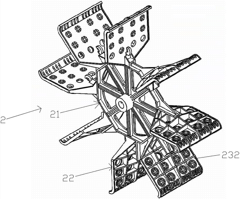
[0042] As shown in the figure, this embodiment discloses an impeller 2 for an aerator, including a blade frame 21 and blades 22, the blade frame 21 and blades 22 are detachably connected, and the blade frame 21 is a regular polygonal structure, any one The side 211 of the polygonal structure is provided with a protruding line 212 which is shorter than the length of the side, the blade is provided with a slot 221 matching with the protruding line, and the blade is provided with a plurality of water holes 222 . Several water holes are arranged in multiple rows and parallel to each other.
[0043] The polygonal structure of the blade frame is a regular polygon, such as a hexagon or an octagon. The use of regular polygons is conducive to the balance of force during installation and use.
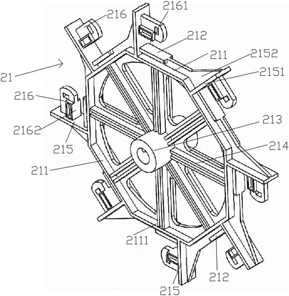
[0044] A sleeve 213 is arranged at the center of the polygonal structure of the blade frame, and the sleeve 213 is connected to the inner side 2111 of any side 211 of the polygonal structure thr...
Embodiment 2
[0047]Different from Embodiment 1, the detachable connection between the blade frame 21 and the blade 22 in this embodiment is not limited to the mating connection between the convex strip and the slot, but also includes a further connection, the connection between the plug 216 and the socket 223 . Specifically, on any side 211 of the polygonal structure, a protruding portion 215 protruding outward is provided, and an inserting block 216 parallel to the protruding strip 212 is provided on the protruding portion 215, and an inserting block 216 corresponding to the inserting block 216 is provided on the blade 22. Socket 223, the installation connection of the blade and the blade frame is realized through the plug-in block and the socket. One end of the protrusion 212 is in contact with the protrusion 215 .
[0048] The insert block is provided with a "convex"-shaped side facing the protruding strip, that is, the inner surface 2162 of the insert block shown in the figure, and the...
Embodiment 3
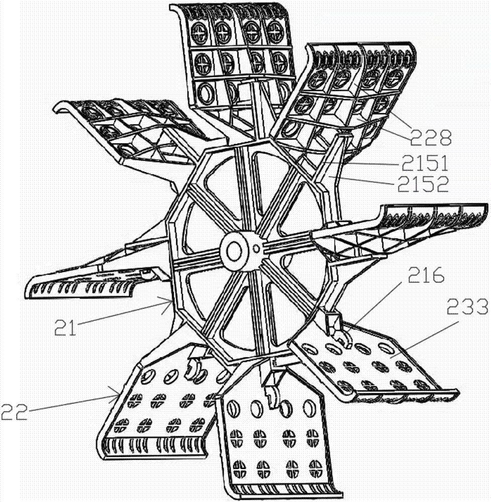
[0050] Different from Embodiment 2, the structure of the raised part 215 in this embodiment is composed of a first flat plate 2151 and a second flat plate 2152, both of which are perpendicular to each other, the first flat plate 2151 is perpendicular to the convex strip 212, and the convex strip 212 is perpendicular to the convex strip 212. The two flat plates 2152 are respectively located on two sides of the first flat plate, and the inserting block 216 is arranged on the surface of the first flat plate provided with the protruding line 212 , and the inserting block 216 is perpendicular to the first plate 2151 and parallel to the protruding line 212 .
[0051] In this embodiment, the first flat plate adopts a rectangular plate, and the second flat plate adopts a triangular plate, which is the best. A side of the inserting block 216 away from the first flat plate 2151 adopts an arc-shaped curved surface.
PUM
 Abstract
Description
Claims
Application Information