A mechanical claw for mechanical manufacturing

A technology of machinery manufacturing and mechanical jaws, applied in the field of machinery manufacturing supporting equipment, can solve the problems of reducing the production efficiency of the production line, poor mechanical strength of the mechanical jaws, and high cost, and can increase the connection stability, increase the mechanical strength, and reduce the failure rate. Effect

Active Publication Date: 2020-04-21
SOUTHEAST UNIV
View PDF4 Cites 0 Cited by
  • Summary
  • Abstract
  • Description
  • Claims
  • Application Information

AI Technical Summary

Problems solved by technology

[0002] In the process of automatic assembly, processing or production, grippers are widely used in the clamping and transfer of various workpieces, while the traditional mechanical grippers are complex in structure, high in cost and cumbersome to use, so there are some The mechanical gripper with a relatively simple structure can reduce the production cost, but the machine needs to run for a long time during automatic transfer. The mechanical strength of the mechanical gripper with a simple structure is poor, and it works well in some mechanical processing with a low degree of automation. , 3. In the mechanical manufacturing production with a high degree of automation, the failure rate is high. When replacing the mechanical grippers, the equipment needs to be stopped. However, after the equipment stops, it will seriously affect the normal operation of the entire production line, and even the entire production line needs to be stopped. , reduce the production efficiency of the production line, so it is necessary to design a mechanical claw for mechanical manufacturing with strong adaptability

Method used


Image

  • A mechanical claw for mechanical manufacturing
  • A mechanical claw for mechanical manufacturing
  • A mechanical claw for mechanical manufacturing

Examples


Embodiment

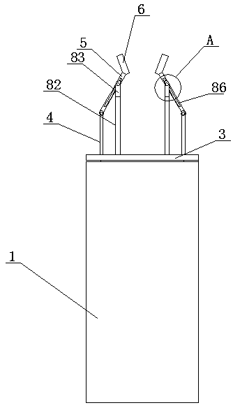
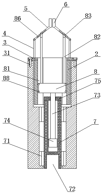
[0027]A mechanical gripper for mechanical manufacturing, comprising an outer sleeve 1, a first inner cavity is arranged at the front end of the outer sleeve 1, and an inner sleeve 2 is arranged in the first inner cavity, and the inner sleeve 2 and the outer sleeve 2 are connected to each other. The sleeve 1 is screwed, the inner sleeve 2 protrudes from the outer sleeve 1 and is provided with a mounting seat 3, and also includes a screw 31, and the mounting seat 3 and the outer sleeve 1 are fixedly connected by the screw 31. The mounting base 3 is provided with a column 4, and the end of the column 4 away from the mounting base 3 is provided with a mechanical clamp arm 5. The clamping block 6 is provided with anti-slip lines 61 on the clamping side of the clamping block 6 , and the anti-slip lines 61 are wave-shaped, and the wave-shaped anti-slip lines 61 on the two clamping blocks 6 are alternately arranged. The rear end of the outer sleeve 1 is provided with a second inner ca...


PUM


Abstract

The invention discloses a mechanical claw used for mechanical manufacture. The mechanical claw comprises an outer sleeve; a first inner cavity is arranged at the front end of the outer sleeve, and an inner sleeve is arranged in the outer sleeve; the inner sleeve is in threaded connection with the outer sleeve; the inner sleeve extends out of the outer sleeve and is provided with an installing seat; the installing seat is provided with a vertical column, and a mechanical clamping arm is arranged at the end, far away from the installing seat, of the vertical column; the mechanical clamping arm is connected with the vertical column in a hinged mode; a clamping block is arranged at the end, far away from the vertical column, of the mechanical clamping arm; a second inner cavity is arranged at the rear end of the outer sleeve; and the second inner cavity is internally provided with a lifting mechanism used for controlling rotating of the mechanical clamping arm. The mechanical claw has the beneficial effects that a lifting cylinder and a lifting column are reinforced through the outer sleeve and the inner sleeve, the mechanical strength of a mechanical clamping claw is enhanced, the failure rate in actual production is reduced, and the mechanical claw used for mechanical manufacture can be better applied to mechanical machining with a high automation degree.

Description

technical field [0001] The invention relates to the field of mechanical manufacturing supporting equipment, in particular to a mechanical claw for mechanical manufacturing. Background technique [0002] In the process of automatic assembly, processing or production, grippers are widely used in the clamping and transfer of various workpieces, while the traditional mechanical grippers are complex in structure, high in cost and cumbersome to use, so there are some The mechanical gripper with a relatively simple structure can reduce the production cost, but the machine needs to run for a long time during automatic transfer. The mechanical strength of the mechanical gripper with a simple structure is poor, and it works well in some mechanical processing with a low degree of automation. , 3. In the mechanical manufacturing production with a high degree of automation, the failure rate is high. When replacing the mechanical grippers, the equipment needs to be stopped. However, after...

Claims


Application Information

Patent Timeline
Patent Type & Authority Patents(China)
IPC IPC(8): B25J15/00
CPCB25J15/00
Inventor 刘家铭
Owner SOUTHEAST UNIV
Why Eureka
Try Eureka