
Electronic parking executing mechanism of vehicle braking system

An electronic parking and actuator technology, applied in the direction of brake actuator, brake type, gear transmission mechanism, etc., can solve the problems of poor energy conversion effect of the actuator, affecting the service brake and parking brake, etc., to achieve maintenance. Easy, improve stability, meet the effect of power transmission

Inactive Publication Date: 2017-11-24
浙江桔子花开实业有限公司
View PDF1 Cites 2 Cited by
  • Summary
  • Abstract
  • Description
  • Claims
  • Application Information

AI Technical Summary

Problems solved by technology

[0003] Electronic parking actuator for vehicle braking system announced by the State Intellectual Property Office of China (application number: 2016203480518, announcement number: CN205632470, announcement date: 2016.10.12), including an upper shell, a lower shell, a motor, and an energy transmission mechanism and the deceleration mechanism, the motor, the energy transmission mechanism and the deceleration mechanism are arranged in the inner cavity formed by the upper shell and the lower shell, the motor is connected with the deceleration mechanism through the energy transmission mechanism, the upper shell is provided with a center column of the upper shell, and the lower shell is The center hole of the lower shell is set corresponding to the position of the center column of the upper shell. Although the process requirements of this structure are relatively low and the production efficiency is improved, the energy conversion effect of the actuator is poor, which affects the driving brake and parking system. verb: move

Method used


Image

  • Electronic parking executing mechanism of vehicle braking system
  • Electronic parking executing mechanism of vehicle braking system

Examples


Embodiment Construction

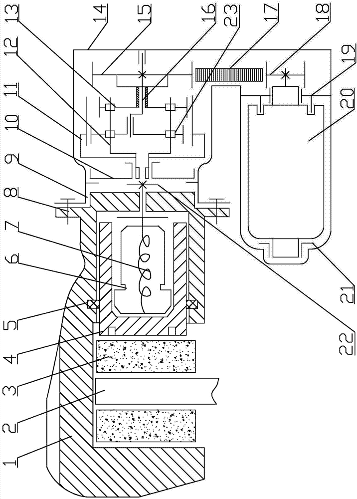
[0023] like Figure 1 to Figure 2 As shown, it is an electronic parking actuator of a vehicle braking system according to the present invention, which includes a transmission device and a brake caliper assembly. The brake caliper assembly includes a sliding screw transmission mechanism 104, a piston 4, a friction block assembly 3 and a brake The moving caliper body 1, the sliding screw transmission mechanism 104, the piston 4 and the friction block assembly 3 are all located in the brake caliper body 1, the sliding screw transmission mechanism 104 includes a threaded push rod 7 and a threaded push rod sleeve 6, and the threaded push rod 7 The protruding end is connected to the involute less-tooth-difference planetary gear transmission mechanism 103 through a spline, and the threaded push rod 7 is provided with a retaining ring 22, and the other end of the threaded push rod 7 and the threaded push rod sleeve 6 adopt a self-locking zigzag thread Connected and limited inside the ...


PUM


Abstract

The invention discloses an electronic parking actuator of a vehicle braking system, which includes a transmission device and a brake caliper assembly. The transmission device includes a front shell and a rear shell, and the transmission device and the brake caliper body are connected by fixing bolts. , a DC motor is arranged under the inner side of the front housing, the DC motor is connected to a battery, and a synchronous belt transmission mechanism is installed on the output shaft of the DC motor. The involute small-tooth-difference planetary gear transmission mechanism is located between the front housing and the rear housing, and the involute small-tooth-difference planetary gear transmission mechanism and the front housing are connected through an internal gear seat. Compared with the traditional actuator of the parking brake system of the rear wheel of the vehicle, the present invention has the advantages of saving cab space, easy operation, labor-saving and stable parking, does not vary from person to person, prevents accidental release, and makes the parking brake safer and more reliable. , It is easy to adopt the advantages of intelligent control and integration of other functions.

Description

technical field [0001] The invention relates to an electronic parking actuator of a vehicle braking system. Background technique [0002] In the caliper-type electronic parking brake system, the motor provides power for the caliper-type parking actuator, the power is transmitted to the reduction mechanism through the transmission, and then the mechanical energy is transmitted to the caliper through the output shaft to achieve the parking effect. The center distance between the motor and the reduction mechanism needs to be a fixed value to ensure the output performance and stability of the transmission mechanism. [0003] Electronic parking actuator for vehicle braking system announced by the State Intellectual Property Office of China (application number: 2016203480518, announcement number: CN205632470, announcement date: 2016.10.12), including an upper shell, a lower shell, a motor, and an energy transmission mechanism and the deceleration mechanism, the motor, the energy ...

Claims


Application Information

Patent Timeline
IPC IPC(8): F16D55/02F16D65/18F16D121/04F16D121/24F16D125/40F16D125/44F16D125/50
CPCF16D55/025F16D65/186F16D2121/04F16D2121/24F16D2125/40F16D2125/44F16D2125/50
Inventor 谢常发吴会明戴国建
Owner 浙江桔子花开实业有限公司
Learn More