Boiler heating type feed dehumidifying and drying device

A drying equipment and heating technology, applied in lighting and heating equipment, drying, drying machines, etc., can solve the problems of unfavorable feed drying treatment, long drying time, waste of resources, etc., and achieve the heating effect conveniently and quickly , improve the quality and effect, and improve the effect of nesting efficiency

Inactive Publication Date: 2017-11-24
赵娜
View PDF0 Cites 4 Cited by
  • Summary
  • Abstract
  • Description
  • Claims
  • Application Information

AI Technical Summary

Problems solved by technology

Moreover, the feed will also be damp during storage, and it is necessary to dry the damp feed again in time, otherwise the feed will deteriorate and become unusable, resulting in a waste of resources
[0003] At present, there are many devices for drying feed, such as gas direct fire drying devices, electric heating drying devices or drying devices such as fans and radiators. Among them, gas direct fire drying devices are suitable for small batches of feed. Drying, the drying speed is slow, the cost is high, the feed cannot be dried evenly, and the drying effect is poor; the electric heating and drying device has potential safety hazards
In addition, the above-mentioned drying device needs to perform a certain treatment on the feed before drying, and the operation is complicated.
And during the drying process, the feed is directly poured into the drying equipment, often because the feed is piled up together to cause uneven heating, low heating efficiency, poor drying effect, poor heat flow inside the oven and drying time Longer, and the drying effect of the feed is poor; and it affects the output of the feed, which is easy to cause blockage, which is not conducive to the drying process of the feed

Method used


Image

  • Boiler heating type feed dehumidifying and drying device
  • Boiler heating type feed dehumidifying and drying device
  • Boiler heating type feed dehumidifying and drying device

Examples


Embodiment Construction

[0021] The following will clearly and completely describe the technical solutions in the embodiments of the present invention with reference to the accompanying drawings in the embodiments of the present invention. Obviously, the described embodiments are only some of the embodiments of the present invention, not all of them. Based on the embodiments of the present invention, all other embodiments obtained by persons of ordinary skill in the art without making creative efforts belong to the protection scope of the present invention.

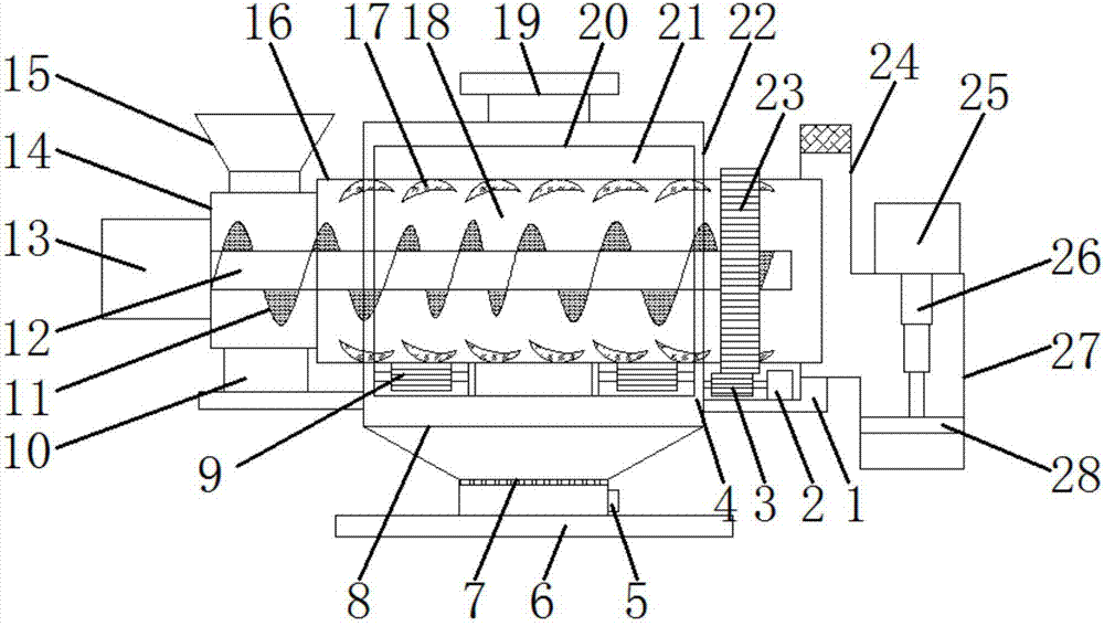
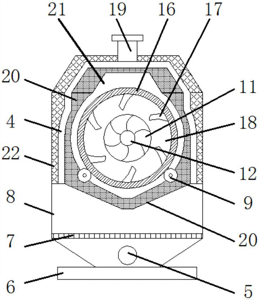
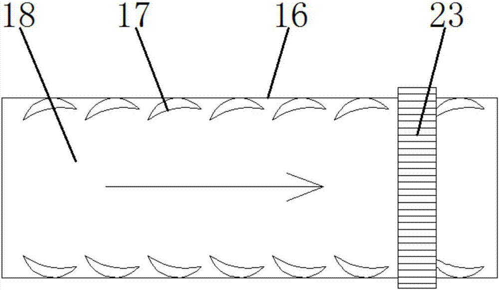
[0022] see Figure 1~3 , in the embodiment of the present invention, a boiler heating type feed dehumidification and drying equipment includes a base 6, a drying drum 16, a heat-conducting inner furnace body 20 and an outer heat-retaining furnace body 22, and an outer heat-retaining furnace is installed on the base 6 body 22, the thermal insulation outer furnace body 22 is provided with a heat-conducting inner furnace body 20, a flue gas passage ...


PUM


Abstract

The invention discloses a boiler-heating type feed dehumidification and drying equipment, which comprises a base, a drying drum, a heat-conducting inner furnace body and a heat-retaining outer furnace body. There is a heat-conducting inner furnace body, a flue gas passage is set between the heat-conducting inner furnace body and the heat-insulating outer furnace body, a chimney is installed on the top of the heat-insulating outer furnace body, and the chimney communicates with the flue gas passage, and the heat-conducting inner furnace body is below The thermal insulation outer furnace body is set as a combustion furnace; the heat-conducting inner furnace body is provided with a heating furnace cavity, and a drying drum is worn in the heating furnace cavity; the heat-conducting inner furnace body has good heat conduction effect and can evenly distribute heat. Realize the full utilization of the heat generated by combustion, the heating effect is good and the heating is uniform; the tumbling and stirring of the feed is improved to avoid the accumulation of the feed on the inner wall of the drying drum, which improves the uniformity of the feed mixing, which is conducive to the full heating and drying of the feed, and improves the Improve the quality and effect of feed drying and improve the discharge efficiency of feed.

Description

technical field [0001] The invention relates to the technical field of feed processing equipment, in particular to boiler heating feed dehumidification and drying equipment. Background technique [0002] With the continuous development of the breeding industry, the demand for feeding feed is also increasing. Therefore, the demand and requirements for feed processing are also increasing. With the continuous application of various feed processing devices in the whole process of feed processing, people often need to dry the feed before the feed is packaged. Whether the feed is dried or not directly reflects its shelf life. Moreover, the feed will also be damp during storage, and it is necessary to dry the damp feed again in time, otherwise the feed will deteriorate and become unusable, resulting in a waste of resources. [0003] At present, there are many devices for drying feed, such as gas direct fire drying devices, electric heating drying devices or drying devices such as ...

Claims


Application Information

Patent Timeline
Patent Type & Authority Applications(China)
IPC IPC(8): F26B11/06F26B23/02F26B25/04
CPCF26B11/0481F26B23/02F26B25/04
Inventor 赵娜
Owner 赵娜
Why Eureka
Try Eureka