
Soaking plate structure

A technology of vapor chamber and support structure, which is applied in indirect heat exchangers, lighting and heating equipment, etc., and can solve problems such as unfavorable steam diffusion, small steam channels, and unfavorable vapor chambers

Pending Publication Date: 2017-11-24
SOUTH CHINA UNIV OF TECH +1
View PDF4 Cites 2 Cited by
  • Summary
  • Abstract
  • Description
  • Claims
  • Application Information

AI Technical Summary

Problems solved by technology

[0004] 1. If the column support structure is used, when the column and the shell are integrally formed, the processing is difficult and the cost is high; when the column and the shell are independent structures, it is necessary to arrange the columns and make The process is more complicated
[0005] 2. If the support methods of Chinese patent applications CN102374808A and CN101566440B are used, since the maximum gap in the plane direction of the metal braid is less than or equal to the diameter of the braided copper wire, the steam channel in the plane direction is small, which is not conducive to steam diffusion. In order to increase the plane direction If there is a gap, the diameter of the copper wire must be increased, but this also increases the overall thickness of the woven wire mesh, which is not conducive to the production of vapor chambers with different thickness requirements.
In addition, the compressibility of the woven wire mesh is not good. In order to obtain a better supporting effect, it is required to strictly control the flattening accuracy of the vapor chamber, which puts forward higher requirements for processing.
For example: when the degree of flattening is not enough to make the woven wire mesh adhere to the upper and lower sides, the woven wire mesh cannot play a supporting role; when the flattening is excessive, the supporting point of the woven wire mesh is easy to damage the capillary liquid-absorbing core structure in contact with it, At the same time, it may cause uneven force on the shell plate, resulting in uneven surface

Method used


Image

  • Soaking plate structure
  • Soaking plate structure
  • Soaking plate structure

Examples


Embodiment 1

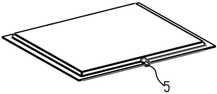
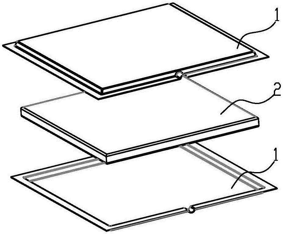
[0035] A vapor chamber structure, comprising an upper shell 1 and a lower shell 2 snapped together, a support structure is provided between the upper shell 1 and the lower shell 2, and the upper shell 1 and the lower shell 2 are covered To support the supporting structure, the lower surface of the upper shell plate 1 is affixed to the upper surface of the supporting structure, and the upper surface of the lower shell plate 2 is affixed to the lower surface of the supporting structure. The supporting structure includes such as Figure 11 As shown in the porous structure layer 3, the porous structure layer 3 is made of a porous material with a pore density of 5-30 ppi and a porosity of 80%-99%.

[0036] The support structure also includes several layers of capillary liquid-absorbing core layers 4 , and the several layers of capillary liquid-absorbing core layers 4 are fixedly connected to the porous structure layer 3 . The porous structure layer 3 is made of metal porous materia...

Embodiment 2

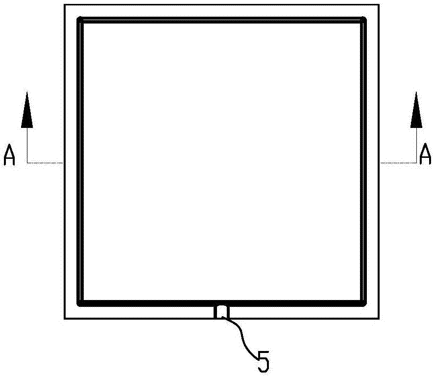
[0042] The main structure of this embodiment is the same as that of Embodiment 1, and the similarities will not be repeated here. The difference is that the structure of the vapor chamber in this embodiment is as follows Figure 5 , Figure 6 , Figure 7 shown. A capillary liquid-absorbing core layer 4 is arranged between the lower shell plate 2 and the porous structure layer 3, the upper surface of the porous structure layer 3 is fixedly connected to the groove surface of the upper shell plate 1, and the lower surface of the porous structure layer 3 is connected to the capillary suction core layer. The upper surface of the liquid core layer 4 is affixed, and the lower surface of the capillary liquid-absorbing core layer 4 is affixed to the groove surface of the lower shell plate 2, so as to play a supporting role. The surrounding edges of the upper shell plate 1 and the lower shell plate 2 are closely connected. Fit and connect, then inject working fluid through liquid inje...

Embodiment 3

[0044] The main structure of this embodiment is the same as that of Embodiment 1 or 2, and the similarities will not be repeated here. The difference is that the vapor chamber structure in this embodiment is as follows Figure 8 , Figure 9 , Figure 10shown. A capillary liquid-absorbing core layer 4 is arranged between the upper shell plate 1, the lower shell plate 2 and the porous structure layer 3, and the upper and lower surfaces of the porous structure layer 3 are respectively fixed with one side of the capillary liquid-absorbing core layer 4 located above and below it. The upper surface of the upper capillary liquid-absorbing core 4 is affixed to the groove surface of the upper shell plate 1, and the lower surface of the lower capillary liquid-absorbing core 4 is affixed to the groove surface of the lower shell plate 2, thereby playing a supporting role , the edges of the upper shell plate 1 and the lower shell plate 2 are tightly fitted and connected, and then the wor...


PUM

PropertyMeasurementUnit
Hole densityaaaaaaaaaa

Abstract

The invention relates to a soaking plate structure. The soaking plate structure comprises an upper shell plate and a lower shell plate which are buckled together, wherein a support structure is arranged between the upper shell plate and the lower shell plate; the support structure is coated with the upper shell plate and the lower shell plate; a lower surface of the upper shell plate is fixedly connected to an upper surface of the support structure; an upper surface of the lower shell plate is fixedly connected to a lower surface of the support structure; the support structure comprises a porous structure layer; the porous structure layer is made from a porous material; and the porous material has a pore density of 5-30ppi and a porosity of 80%-99%. The porous material with a low pore density and a high porosity is taken as the support structure of a soaking plate, and the structure is uniform in support point position distribution, high in density, reliable in support effect, free from influence on heat transfer performance of the soaking plate, capable of being used for manufacturing soaking plates with various shapes, simple to produce, low in cost, and suitable for batch production.

Description

technical field [0001] The invention relates to the field of heat transfer devices, in particular to a vapor chamber structure. Background technique [0002] The support structure of the existing vapor chamber usually adopts columns regularly arranged between the upper and lower shell plates to play a supporting role. Chinese patent applications CN102374808A and CN101566440B disclose a vapor chamber, which adopts opposite sides of a metal braided mesh to respectively abut against opposite sides of a housing for support. [0003] The problem that prior art exists is: [0004] 1. If the column support structure is used, when the column and the shell are integrally formed, the processing is difficult and the cost is high; when the column and the shell are independent structures, it is necessary to arrange the columns and make The process is more complicated. [0005] 2. If the support methods of Chinese patent applications CN102374808A and CN101566440B are used, since the ma...

Claims


Application Information

Patent Timeline
IPC IPC(8): F28D15/04
CPCF28D15/046
Inventor 黄光文李勇周文杰何柏林陈韩荫陈创新
Owner SOUTH CHINA UNIV OF TECH
Learn More