
Rotor system dynamic balance excitation identification method

An identification method and rotor vibration technology, applied in the field of mechanical vibration, can solve the problems of increasing the difficulty of obtaining the unbalanced excitation force of the rotor, the limited position and method of adding counterweights, and insufficient consideration of on-site dynamic balance requirements, so as to achieve easy learning and The effect of promotion, cost reduction and manpower investment

Active Publication Date: 2017-11-24
HARBIN ENG UNIV
View PDF4 Cites 20 Cited by
  • Summary
  • Abstract
  • Description
  • Claims
  • Application Information

AI Technical Summary

Problems solved by technology

[0005] In summary, all kinds of dynamic balancing methods have certain shortcomings and limitations.
At present, vertical pump equipment such as centrifugal pumps and screw pumps driven by marine motors do not take into account the requirements for on-site dynamic balance, which leads to severe restrictions on the position and method of adding counterweight, and the measurement position of rotor vibration is also very limited, which increases the size of the rotor. It is difficult to obtain unbalanced excitation force, therefore, the acquisition and identification methods of unbalanced force and unbalanced torque are still technical problems that need to be solved urgently

Method used


Image

  • Rotor system dynamic balance excitation identification method
  • Rotor system dynamic balance excitation identification method
  • Rotor system dynamic balance excitation identification method

Examples


Embodiment Construction

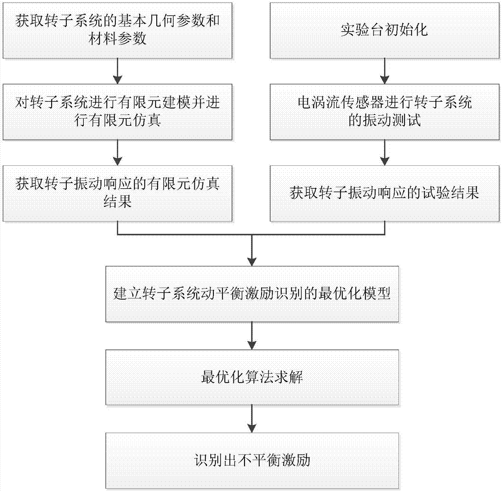
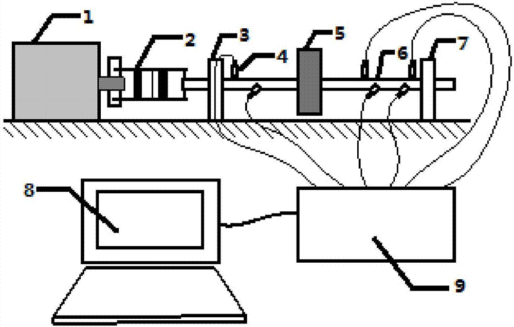
[0024] The following combination figure 1 flowchart and figure 2 Embodiment describes the present invention in detail:

[0025] Technical solution one:

[0026] Such as figure 1 As shown, the specific implementation steps of the rotor system dynamic balance excitation identification method described in the present invention are as follows:

[0027] Step 1. Collection of experimental data

[0028] a) combine figure 2 Carry out the construction of the rotor test bench, which mainly includes: motor 1, coupling 2, left end bearing 3, eddy current sensor 4, disk 5, rotating shaft 6, right end bearing 7, computer 8 and signal acquisition instrument 9. The motor 1 is connected to the rotating shaft 6 through the coupling 2, the disc 5 is installed at the center of the rotating shaft, the rotating shaft is supported by the left end bearing 3 and the right end bearing 7, and the eddy current sensor transmits the signal to the signal acquisition instrument 9, and finally through ...


PUM


Abstract

A rotor system dynamic balance excitation identification method is disclosed. The method is characterized by carrying out experiment determination; collecting output of an eddy current sensor on a rotating shaft and acquiring an actual measurement value of a rotor vibration response; when a motor stops rotating, collecting a geometrical parameter and a material parameter of a rotor system and establishing a finite element model of the rotor system; through finite element simulation, acquiring a simulation value of the rotor vibration response; setting a rotor system dynamic balance excitation identification target function and an optimization model; and using an optimization algorithm to carry out iteration solution and acquiring an initial imbalance amount, bearing rigidity and a damping parameter of the rotor system. By using the method, a simulation result and an experiment result are optimized; based on parts of experiment data, through rotor system dynamic balance excitation possessing good robustness and identification precision, effective identification is performed; the method can be easily applied to actual engineering; and an application is less limited by an equipment result and a test condition.

Description

technical field [0001] The invention belongs to the field of mechanical vibration, in particular to a dynamic balance excitation identification method of a rotor system. Background technique [0002] The identification of unbalanced excitation force of rotating machinery is closely related to the dynamic balance theory of rotor system. At present, the rotor dynamic balancing process is mainly realized on the dynamic balancing machine. Only some ship machinery, such as steam turbines, generators and other large-scale equipment, have technical requirements for on-site dynamic balancing. For auxiliary power equipment, on-site dynamic balancing operations are rarely performed. There is also a lack of effective quantitative analysis methods for the unbalanced incentive force during operation. [0003] Engineering practice shows that the unbalanced excitation of the rotor during the operation of vertical mechanical equipment such as motor-driven centrifugal pumps and screw pumps ...

Claims


Application Information

Patent Timeline
Patent Type & Authority Applications(China)
IPC IPC(8): G01M1/16G01M1/22G01M5/00
CPCG01M1/16G01M1/22G01M5/0075
Inventor 陈美龙李玩幽王东华黄健哲赵滨高奇刘凯旋刘震乐帅
Owner HARBIN ENG UNIV
Learn More