Weather radar levelness automatic measuring system

A level measurement, weather radar technology, applied in radio wave measurement system, measuring device, measuring inclination, etc., can solve the problems of high labor intensity, long measurement time, cumbersome process, etc., and achieve low power consumption design and realization Long-term automatic non-contact measurement to realize the effect of power consumption design

Pending Publication Date: 2021-03-16
CMA METEOROLOGICAL OBSERVATION CENT
View PDF0 Cites 3 Cited by
  • Summary
  • Abstract
  • Description
  • Claims
  • Application Information

AI Technical Summary

Problems solved by technology

Measuring the levelness of the weather radar base has long been a difficult task. The antenna aperture size reaches 4.3m, and the antenna feed height reaches more than ten meters. Eight positions of 225°, 270°, 315°, and 360° are used for level measurement. For each measurement, the pitch angle is set to 0°, and the antenna rotates 45° to stop. Manually climb to a platform of more than ten meters to place a composite image level. Start measurement after stabilization, manual reading and conversion. After completion, climb down the platform, remove the ladder, turn on the radar, and then rotate 45° for measurement. Repeat this until 360°. Frequently lift the ladder and climb up the platform for measurement. The measurement takes a long time , the process is cumbersome and labor-intensive

Method used


Image

  • Weather radar levelness automatic measuring system
  • Weather radar levelness automatic measuring system
  • Weather radar levelness automatic measuring system

Examples


Embodiment Construction

[0032] The following will clearly and completely describe the technical solutions in the embodiments of the present invention with reference to the accompanying drawings in the embodiments of the present invention. Obviously, the described embodiments are only some, not all, embodiments of the present invention. Based on the embodiments of the present invention, all other embodiments obtained by persons of ordinary skill in the art without making creative efforts belong to the protection scope of the present invention.

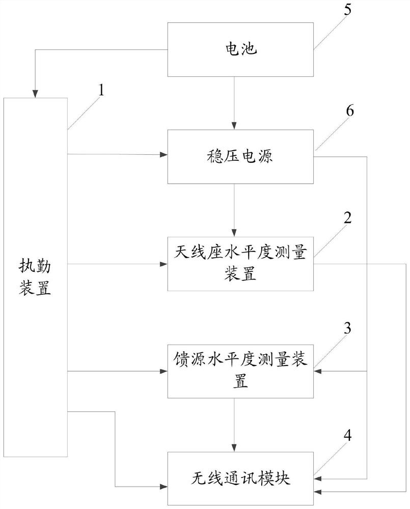
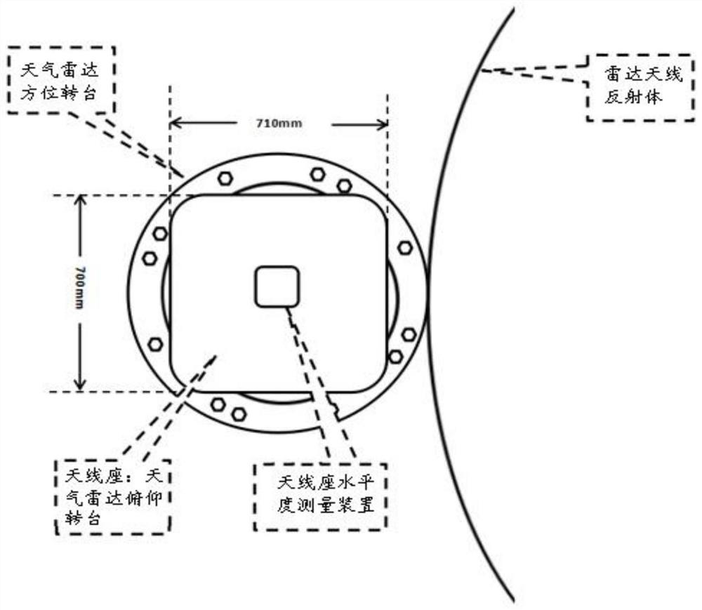
[0033] The purpose of the present invention is to provide a weather radar level automatic measurement system to realize the automatic measurement of feed source level and antenna base level in different azimuths.

[0034] In order to make the above objects, features and advantages of the present invention more comprehensible, the present invention will be further described in detail below in conjunction with the accompanying drawings and specific embodiments. ...


PUM


Abstract

The invention discloses a weather radar levelness automatic measuring system which comprises an on-duty device, an antenna pedestal levelness measuring device, a feed source levelness measuring deviceand a wireless communication module. The on-duty device is used for sending an awakening signal at set time; the antenna pedestal levelness measuring device is used for starting to measure the antenna pedestal levelness in different directions when the pitch angle is 0 degree according to the wake-up signal; the feed source levelness measuring device is used for starting to receive a radar sidelobe radiation signal according to the wake-up signal and calculating the feed source levelness according to the radar sidelobe radiation signal; and the wireless communication module is used for sending the levelness of the antenna pedestal and the levelness of the feed source in different directions to an upper computer for display. By arranging the antenna pedestal levelness measuring device andthe feed source levelness measuring device, the feed source levelness and the antenna pedestal levelness in different directions can be automatically measured, and the problems of long time, complicated process and high labor intensity of traditional measurement are solved.

Description

technical field [0001] The invention relates to the technical field of levelness measurement, in particular to a weather radar levelness automatic measurement system. Background technique [0002] The basis of high-precision measurement of meteorological targets by weather radar is radar calibration, and the level measurement of antenna base is one of the calibration items of weather radar. Measuring the levelness of the weather radar base has long been a difficult task. The antenna aperture size reaches 4.3m, and the antenna feed height reaches more than ten meters. Eight positions of 225°, 270°, 315°, and 360° are used for level measurement. For each measurement, the pitch angle is set to 0°, and the antenna rotates 45° to stop. Manually climb to a platform of more than ten meters to place a composite image level. Start measurement after stabilization, manual reading and conversion. After completion, climb down the platform, remove the ladder, turn on the radar, and then ...

Claims


Application Information

Patent Timeline
Patent Type & Authority Applications(China)
IPC IPC(8): G01S13/95G01S7/40G01C9/00G08C17/02
CPCG01C9/00G01S7/4004G01S13/95G08C17/02Y02A90/10
Inventor 韩旭陈玉宝邵楠步志超刘洁王箫鹏
Owner CMA METEOROLOGICAL OBSERVATION CENT
Why Eureka
Try Eureka