Programmable aperture imaging system based on LCOS spatial light modulator and super-resolution reconstruction method using the same

A technology of spatial light modulator and imaging system, which is applied to parts, instruments, optics, etc. of the TV system, can solve the problems affecting the super-resolution effect and the problem of low-pass effect, and achieve fast measurement, simple structure, and reduced pixelated effect

Active Publication Date: 2017-11-24
NANJING UNIV OF SCI & TECH
View PDF11 Cites 9 Cited by
  • Summary
  • Abstract
  • Description
  • Claims
  • Application Information

AI Technical Summary

Problems solved by technology

Although the masking method can overcome the spectral aliasing problem caused by the distance between the centers of two adjacent CCD pixels, this method ignores the size of the CCD pixel and regards the CCD pixel as an ideal point, which does not solve the problem caused by each pixel of the CCD. The problem of low-pass effect caused by the size and shape of (Liu Jingdan, Xu Tingfa, Xun Xianchao, et al. Simulation of geometric super-resolution imaging by optical mask[J]. Optical Precision Engineering, 2014,22(8):2026-2031.)
In 2013, Liu Haiying and others proposed the use of digital micromirror array (DMD) to achieve super-resolution reconstruction, but the DMD device has a "diffraction grating effect", which affects the super-resolution effect (Liu Haiying, Li Yunsong, Wu Chengke. A digital micromirror array partition Compressed sensing imaging method for control and super-resolution reconstruction[J]. Acta Photonica Sinica, 2013,43(5):510002-0510002.)

Method used


Image

  • Programmable aperture imaging system based on LCOS spatial light modulator and super-resolution reconstruction method using the same
  • Programmable aperture imaging system based on LCOS spatial light modulator and super-resolution reconstruction method using the same
  • Programmable aperture imaging system based on LCOS spatial light modulator and super-resolution reconstruction method using the same

Examples


Embodiment Construction

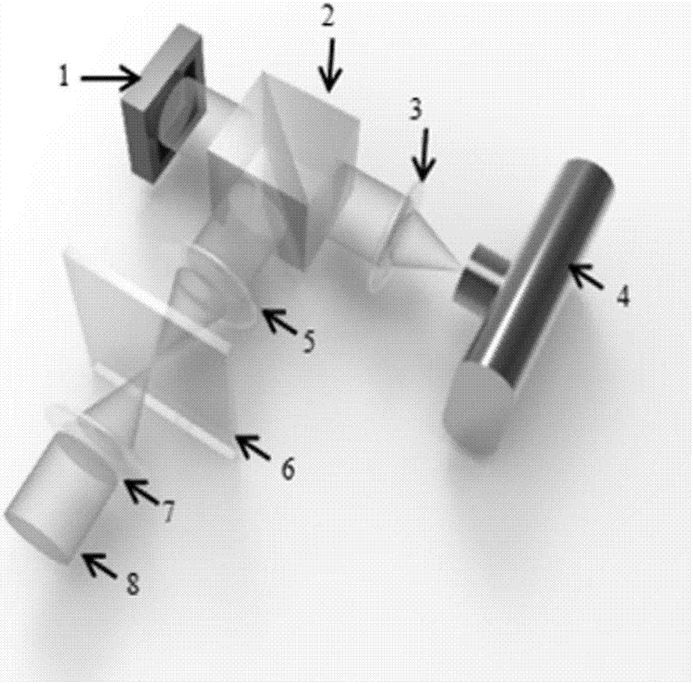
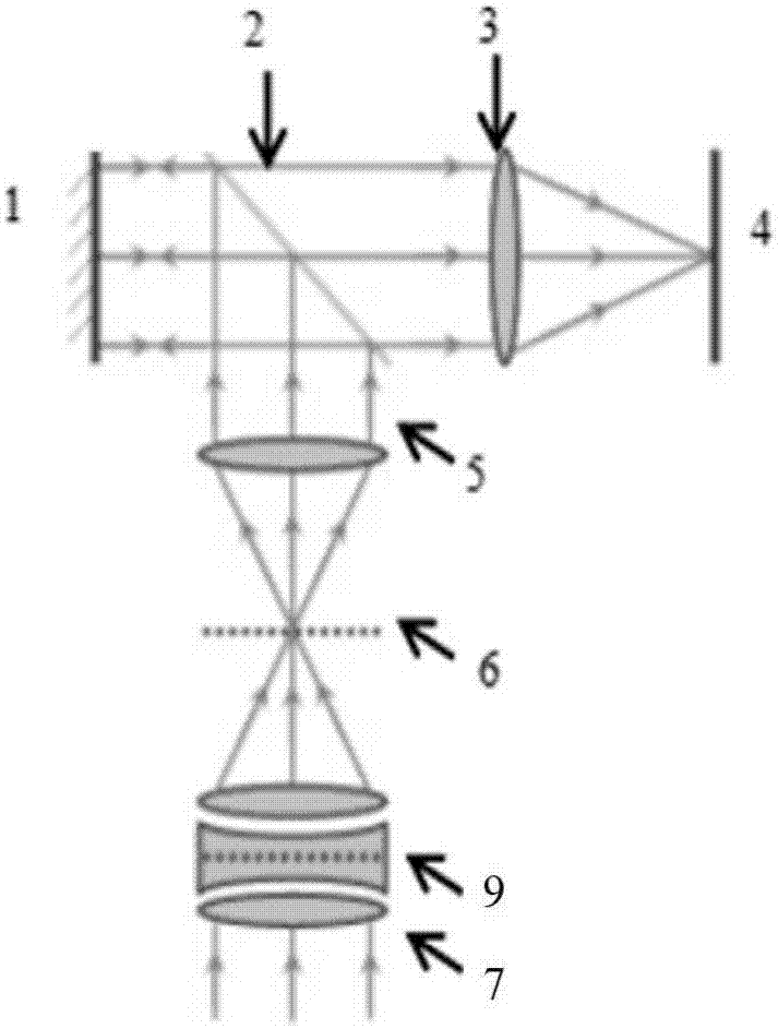
[0013] combine figure 1 , the present invention is based on the programmable aperture imaging system of LCOS spatial light modulator, comprises spatial light modulator 1, optical beam splitter 2, lens two 3, camera 4, lens one 5, imaging main lens group 7, adopts based on 4f system The reflective optical path structure of the 4f system is composed of lens two 3, optical beam splitter 2 and lens one 5. The optical path structure is similar to an "L" shape, and the optical beam splitter 2 is at the turning point of the "L". The distances from the optical beam splitter 2 are equal, and the specific distance is determined by the focal length of the lens used in the 4f system. This optical path structure images the aperture plane 9 of the imaging main lens group 7 onto the spatial light modulator 1, wherein the spatial light modulator 1 is of LCOS (Liquid Crystal on Silicon) type. The spatial light modulator 1 is located on the rear focal plane of lens one 5, and can realize the ...


PUM


Abstract

The invention discloses a programmable aperture imaging system based on an LCOS spatial light modulator and a super-resolution reconstruction method using the same. The programmable aperture imaging system is composed of a spatial light modulator, a beam splitter, a lens II, a camera, a lens I, and an imaging main lens group. The lens II, the beam splitter and the lens I form a 4f system reflective optical path structure; included angles between the beam splitter and the lens II and between the beam splitter and the lens I are 45 degrees; and the distances between the lens II and the beam splitter and between the lens I and the beam splitter and are equal. The aperture plane of the imaging main lens group is imaged on the spatial light modulator; and the spatial light modulator is arranged on a rear focal plane of the lens I and is also arranged on a front focal plane of the lens II. The camera is arranged at the rear focal plane of the 4f system lens II. According to the invention, no mechanical scanning device is needed. Moreover, the programmable aperture imaging system has advantages of simple structure, rapid measurement, and simple operation. And with the LCOS spatial light modulator, the optical grating diffraction effect is avoided.

Description

technical field [0001] The invention belongs to computational imaging technology, in particular to a programmable aperture imaging system and a super-resolution method based on an LCOS spatial light modulator. Background technique [0002] Although the existing photoelectric imaging technology has made great progress and achieved a series of excellent results, neither high-priced professional digital cameras nor cheap mobile phone cameras have broken through the traditional "small hole imaging" method, and are still lens-based "What you see is what you get" imaging mode, although the principle of this mode is simple and easy to operate, there is still an insurmountable limitation - image pixelation. Existing photoelectric imaging systems are limited by the level of detector technology and production costs in terms of information acquisition, specific functions, and performance indicators. Generally speaking, the most straightforward way to solve the problem of image pixelat...

Claims


Application Information

Patent Timeline
Patent Type & Authority Applications(China)
IPC IPC(8): H04N5/225H04N5/232G02B27/58
CPCG02B27/58H04N23/55H04N23/67H04N23/951
Inventor 左超卢林芃陈钱孙佳嵩阚升晨张佳琳李加基顾国华张玉珍
Owner NANJING UNIV OF SCI & TECH
Why Eureka
Try Eureka