Pipe withdrawing device

A tube delivery and cannula technology, applied in the field of tube withdrawal device, can solve problems such as withdrawing from lesion area, blood vessel dissection or tearing, PTCA guide wire movement, etc., to achieve the effect of ensuring smooth progress and convenient withdrawal

Inactive Publication Date: 2017-11-28
APT MEDICAL HUNAN INC
View PDF8 Cites 3 Cited by
  • Summary
  • Abstract
  • Description
  • Claims
  • Application Information

AI Technical Summary

Problems solved by technology

[0004] During the withdrawal of the microcatheter, since the microcatheter is a long and thin tubular structure, there is often a certain amount of friction between the inner wall of the microcatheter lumen and the PTCA guide wire during the withdrawal process. The catheter is taken out of the lesion due to the pulling action, resulting in the failure of PTCA guide wire penetration
At present, normal saline reverse punching technology or extended guide wire technology is generally used clinically to ...

Method used


Image

  • Pipe withdrawing device
  • Pipe withdrawing device
  • Pipe withdrawing device

Examples


Embodiment Construction

[0021] In order to enable those skilled in the art to better understand the technical solutions in the present application, the technical solutions in the embodiments of the present application will be clearly and completely described below in conjunction with the drawings in the embodiments of the present application. Obviously, the described The embodiments are only some of the embodiments of the present application, but not all of them.

[0022] Based on the embodiments in this application, all other embodiments obtained by persons of ordinary skill in the art without creative efforts shall fall within the scope of protection of this application.

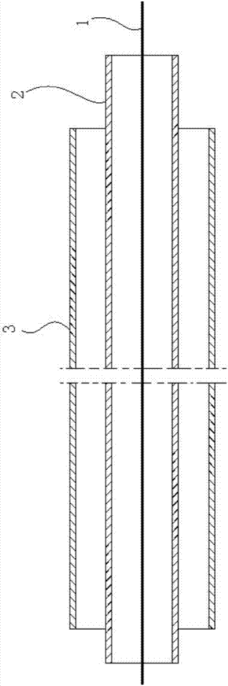
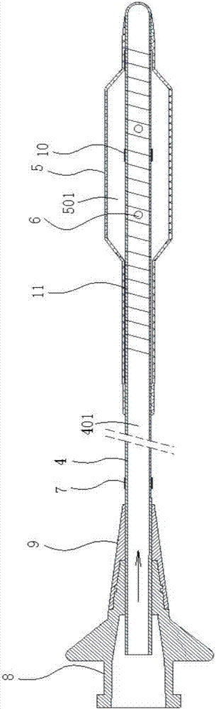
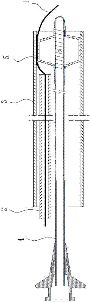
[0023] see figure 2 and image 3 , figure 2 and image 3 A specific embodiment of a pipe withdrawing device of the present invention is provided, wherein, figure 2 It is a schematic diagram of the overall structure of a pipe withdrawal device disclosed in an embodiment of the present invention; image 3 It is a schematic ...


PUM


Abstract

The invention discloses a pipe withdrawing device comprising a hollow-structure push pipe. The front end of the push pipe is closed, and the rear end of the push pipe is open. The outer wall of the front section of the push pipe is sleeved with a telescopic balloon. A through hole is formed between a telescopic balloon inner cavity and a push pipe inner cavity. According to the pipe withdrawing device provided by the invention, when needing to be withdrawn, a micro conduit is moved back first till the front end is withdrawn into a guide conduit, then the pipe withdrawing device provided by the invention is stretched into the guide conduit, the inserting depth is observed through a depth mark till the telescopic balloon of the pipe withdrawing device reaches the position in front of the end of the micro conduit, then gas inflation or transfusion is conducted at an opening in the rear end of the push pipe, gas or liquid enters the telescopic balloon inner cavity through the through hole, thus the telescopic balloon expands and extends till a PTCA guide wire is pressed to the inner wall of the guide conduit, at the moment, the micro conduit continues to be withdrawn and pulled out, then the PTCA guide wire is not moved, and smooth conducting of the percutaneous coronary intervention (PCI) therapeutic technique can be ensured effectively.

Description

technical field [0001] The present invention relates to the technical field of medical instruments, and more specifically, to a tube withdrawing device. Background technique [0002] PCI (Percutaneous Coronary Intervention) refers to a treatment method that dredges the narrowed or even occluded coronary lumen through cardiac catheterization, thereby improving myocardial blood perfusion. PCI treatment has a short course of treatment, less trauma, and significant curative effect And other advantages, so its application is more and more extensive. Among them, the most critical operation in PCI treatment is to pass the PTCA guide wire through the lesion area, so as to establish a track for the follow-up treatment equipment to reach the lesion area. [0003] In the prior art, when the PTCA guide wire passes through the lesion area, it generally needs to be guided and supported by a special guide catheter. Insert it inside. In actual operation, due to the limited reach of the g...

Claims


Application Information

Patent Timeline
IPC IPC(8): A61M25/01A61M25/09
CPCA61M25/0169A61M25/09A61M2025/0186A61M2025/09125
Inventor 黄河成正辉殷望
Owner APT MEDICAL HUNAN INC
Why Eureka
Try Eureka