Engine and cam shaft, cam device and control cam of engine

A technology for controlling cams and cam devices, applied to engines and their camshafts, cam devices, and control cams. field, it can solve the problems of complex groove structure, limited axial movement space of the sleeve, cumbersome processing, etc., and achieve the effect of reducing the difficulty of layout, simple structure and shape, and simplifying the processing technology

Active Publication Date: 2017-11-28
SAIC MOTOR
View PDF8 Cites 9 Cited by
  • Summary
  • Abstract
  • Description
  • Claims
  • Application Information

AI Technical Summary

Problems solved by technology

[0006] The problem solved by the invention is that in the existing engine camshaft, the structure of the groove is complex, the processing is cumbersome, and the axial movement space of each sleeve is limited

Method used


Image

  • Engine and cam shaft, cam device and control cam of engine
  • Engine and cam shaft, cam device and control cam of engine
  • Engine and cam shaft, cam device and control cam of engine

Examples


no. 1 example

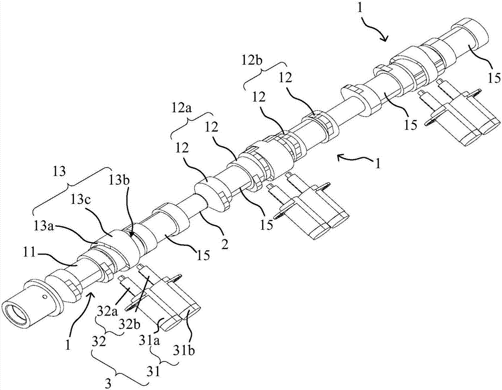
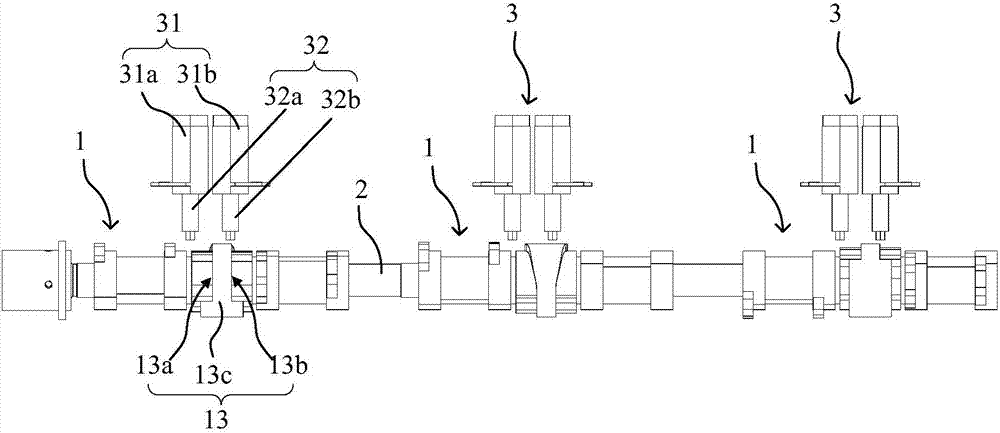
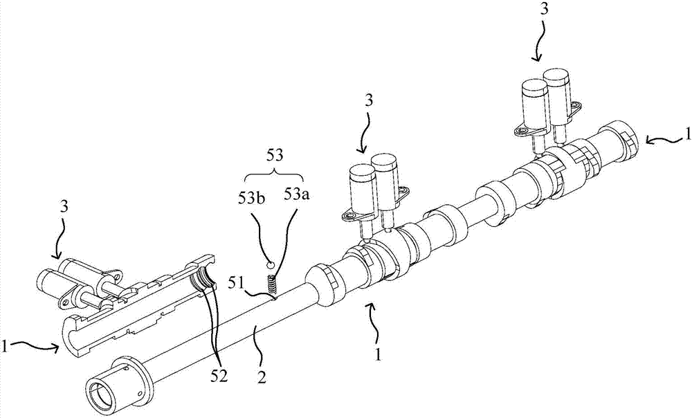
[0043] refer to Figure 1 to Figure 4 As shown, the embodiment of the present invention provides an engine and its camshaft, a cam device 1 and a control cam 13, wherein the control cam 13 is used in the cam device 1 of the engine camshaft. The cam device 1 is used to be sleeved on the mandrel 2, and forms an engine camshaft together with the mandrel 2. The cam device 1 and the mandrel 2 can be connected by splines or other structures, so that the cam device 1 can move along the axial direction of the mandrel 2 .

[0044] The actuator 3 is arranged outside the camshaft and fixed on the cylinder or the cylinder head as a driving part for driving the axial movement of the cam device 1. The actuator 3 can act on the control cam 13 when the cam device 1 needs to move, thereby The cam device 1 is pushed to move in the axial direction of the mandrel 2 .

[0045] In addition to the control cam 13, the cam device 1 also includes a sleeve 11 and a pair of cams 12 arranged on the slee...

no. 2 example

[0080] Such as Figures 11 to 13 As shown, the difference between this embodiment and the first embodiment is that the structure of the control cam is different. In the control cam 13 of this embodiment, the design of the first driving surface 13a and the second driving surface 13b is the same as that of the first embodiment ,Such as Figure 13 , the first driving surface 13a and the second driving surface 13b respectively include an entry section p1, a switching section p2 and an exit section p3 sequentially connected along the circumferential direction of the control cam 13, and the cam device 1 is activated when the switching section p2 cooperates with the actuator 3 drive. In other words, when the actuator 3 is in contact with the entry section p1 or the exit section p3, it cannot push the cam device 1 to move in the axial direction.

[0081] Such as Figures 11 to 13 As shown, the difference between the control cam of this embodiment and the control cam of the first em...

no. 3 example

[0088] This embodiment provides another engine, which differs from the engine of the first embodiment in that the cooperation relationship between the actuator 3 and the control cam 13 is different.

[0089] In this embodiment, the locking pins (i.e. the first locking pin 32a and the second locking pin 32b) of the locking pin portion 32 are not fully stretched out when they are in contact with the end point of the entry segment p1, and are in the process of contacting the switching segment p2. fully extended.

[0090] That is to say, when the lock pin of the lock pin part 32 needs to be stretched out to cooperate with the corresponding driving surface, the lock pin stretches out and enters the entry section p1, and during the movement of the lock pin from the starting point to the end point of the entry section p1, The locking pin is in the process of constantly extending.

[0091] However, when the locking pin moves to the end of the entry section p1, the locking pin has not...


PUM


Abstract

The invention discloses an engine and a cam shaft, a cam device and a control cam of the engine. The control cam is provided with a first driving surface which faces one axial end, a second driving surface which faces the other axial end, and a spacing part which is located between the first driving surface and the second driving surface. The first driving surface and the second driving surface are back to each other, and are spaced by the spacing part; the first driving surface and the second driving surface are used for being coordinated with an execution mechanism separately to enable the cam device to be driven to move axially in different directions. The structure and the shape of the control cam are simpler, the shape and the precision of the driving surfaces are more controllable, means like powder metallurgy and forging are adopted to conduct primary processing and forming, and thus the processing technique is simplified, which is conducive to lowering of the cost.

Description

technical field [0001] The invention relates to the field of automobiles, in particular to an engine and a camshaft thereof, a cam device and a control cam. Background technique [0002] The camshaft is an important part in the engine, which is used to control the opening and closing action of the valves. In a traditional camshaft, several cams are evenly distributed on the camshaft, and the cam and the camshaft are integrally structured, and the cam cannot move axially. [0003] With the development of technology, in order to make the valve lift variable, a new camshaft has appeared. In this camshaft, several cams of each cylinder are integrated on a sleeve, and are installed on the cam through the sleeve. on axis. Each cam has two different lifts arranged in the axial direction, and the sleeve can move axially relative to the camshaft to switch the lifts of the cams. [0004] Among them, the sleeve is provided with two grooves that are respectively matched with the two ...

Claims


Application Information

Patent Timeline
Patent Type & Authority Applications(China)
IPC IPC(8): F01L13/00
CPCF01L13/0036F01L2013/0052
Inventor 郝晓伟李冲霄张卓群戴基卉黄旭白小劲陈新
Owner SAIC MOTOR
Why Eureka
Try Eureka