Experiment device for testing operation performance of bioretention facility

A bioretention and test device technology, which is applied in the field of test devices for testing the operating efficiency of bioretention facilities, can solve the problems of inability to observe the growth of plant roots, the water level in the pool, the inconvenient installation of monitoring devices such as flow meters, and the complexity of bioretention facilities, etc. problems, to achieve the effect of convenient handling and application, strong practicability and convenient operation

Active Publication Date: 2017-11-28
KUNSHAN CONSTRUCT ENG QUALITY TESTING CENT +2
View PDF6 Cites 8 Cited by
  • Summary
  • Abstract
  • Description
  • Claims
  • Application Information

AI Technical Summary

Problems solved by technology

The research on bioretention tanks started relatively late in my country. The existing bioretention tank test devices include underground models that simulate actual conditions, and above-ground types such as test barrels and test chambers, etc., but the functions are relatively single, and the underground type cannot observe plants. The growth of the root system and the water level in the pond, and the installation of monitoring devices such as flow meters is inconvenient. In addition, the simulation of artificial rainfall cannot rule out the interference of actual rainfall events on the test.
[0004] In November 2014, the Ministry of Housing and Urban-Rural Development issued the "Technical Guidelines for Sponge City Construction", which pointed out that hydrological, hydraulic calculations and model simulations can be used to decompose the total annual runoff control layer by layer and analyze step by step, but the situation of bioretention facilities is relatively poor. It is complex and requires actual test data to verify the correctness of the model simulation and calculation, and continuously optimize the model. At the same time, long-term data accumulation also provides a more sufficient basis for the designation of urban planning

Method used


Image

  • Experiment device for testing operation performance of bioretention facility
  • Experiment device for testing operation performance of bioretention facility
  • Experiment device for testing operation performance of bioretention facility

Examples


Embodiment Construction

[0039] The following will clearly and completely describe the technical solutions in the embodiments of the present invention with reference to the accompanying drawings in the embodiments of the present invention. Obviously, the described embodiments are only some, not all, embodiments of the present invention. Based on the embodiments of the present invention, all other embodiments obtained by persons of ordinary skill in the art without creative efforts fall within the protection scope of the present invention.

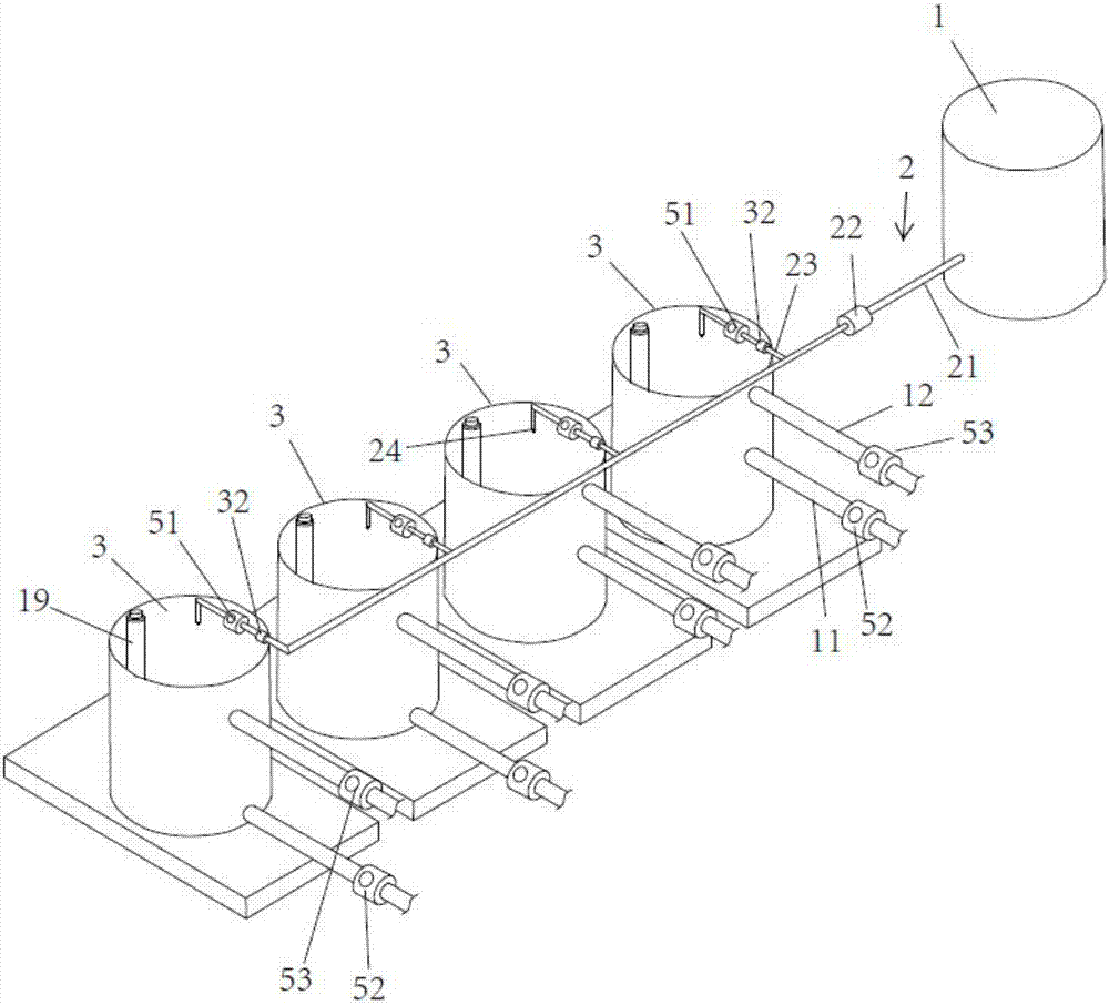
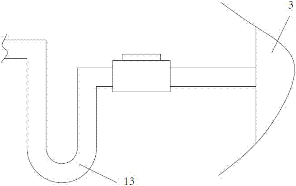
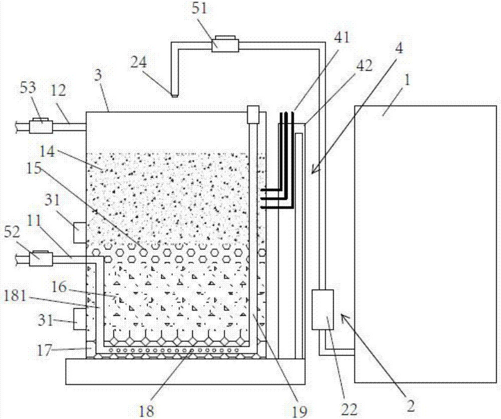
[0040] refer to figure 1 and figure 2 As shown, an embodiment of a test device for detecting the operating efficiency of a bioretention facility of the present invention includes a rainwater collection tank 1, a water delivery system 2, a flow monitoring system, a bioretention tank 3, a permeability coefficient measurement assembly 4 and The electric retractable canopy; the rainwater collection bucket collects rainwater through the roof of the building and the do...


PUM


Abstract

The invention discloses an experiment device for testing operation performance of a bioretention facility. The experiment device comprises a rainwater collecting barrel, a water conveying system, a flow monitoring system, a bioretention barrel, a permeability coefficient measuring assembly and an electric telescopic rainshed. Rainwater in the rainwater collecting barrel is conveyed through a water conveying system and is sprayed into the bioretention barrel for simulating rainfall. The permeability coefficient measuring assembly is used for measuring a permeability coefficient of a filtering layer medium in a rainfall simulating process. The flow measuring system is used for recording rainwater amount which enters and is discharged from the bioretention barrel. The electric telescopic rainshed is arranged above the bioretention barrel. Through extension of the electric telescopic rainshed, entering of natural rainwater into the bioretention barrel can be prevented. The experiment device has advantages of low cost, simple operation, high data reliability, convenient acquisition and effective recyclability. The experiment device can simulate a hydrological and water quality effect of the biotention barrel on the conditions such as different rainfall types, different filler proportions and different plant kind. The related basic research has an important meaning for promoting construction of the sponge city.

Description

technical field [0001] The invention relates to the technical field of sponge city construction, in particular to a test device for detecting the operating efficiency of biological retention facilities. Background technique [0002] Sponge city is a new generation of urban rain and flood management concept. It follows the principles of ecological priority and combines natural methods with artificial measures to maximize the accumulation of rainwater in urban areas while ensuring the safety of urban drainage and waterlogging. Infiltration and purification, promote the utilization of rainwater resources and ecological environment protection. The construction of "sponge city" is not to overthrow and replace the traditional drainage system, but to "reduce the burden" and supplement the traditional drainage system, to maximize the role of the city itself, to absorb, store and seep water when it rains , Purify water, "release" the stored water and use it when needed. [0003] A ...

Claims


Application Information

Patent Timeline
IPC IPC(8): G01D21/00
CPCG01D21/00Y02A20/108
Inventor 顾盛杨飞凯崔咏军傅大放
Owner KUNSHAN CONSTRUCT ENG QUALITY TESTING CENT
Why Eureka
Try Eureka