Laser welding apparatus and laser welding method

A laser welding, laser technology, applied in laser welding equipment, welding equipment, manufacturing tools and other directions, can solve the problems of coloring, low transparency, opacity and so on

Inactive Publication Date: 2017-11-28
SEIDENSHA ELECTRONICS
View PDF12 Cites 7 Cited by
  • Summary
  • Abstract
  • Description
  • Claims
  • Application Information

AI Technical Summary

Problems solved by technology

Since pigments such as carbon black are added to the laser-absorbing plastic plate 302 or the laser-absorbing material 306, there is a problem that it may be colored and opaque, or even if it is translucent, the transparency is low.

Method used


Image

  • Laser welding apparatus and laser welding method
  • Laser welding apparatus and laser welding method
  • Laser welding apparatus and laser welding method

Examples


no. 1 approach

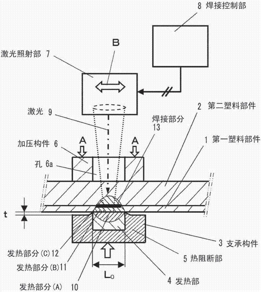
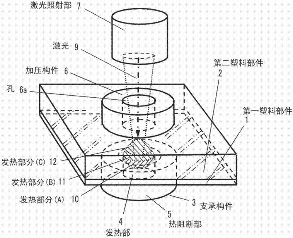
[0108] The principle of the laser welding method for the first and second plastic parts 1 and 2 will be described as a laser welding method for a plurality of plastic parts that transmits laser light according to the first embodiment of the present invention. figure 1 is a sectional view of the main part in the first embodiment, figure 2 is a stereogram.

[0109] figure 1 Among them, 1 and 2 are a plurality of plastic parts to be welded. Here, a method of welding the first plastic part 1 and the second plastic part 2 as a plurality of plastic parts will be described. For the case where the welding object is set to 3 plastic parts, use later Figure 6 to explain.

[0110] Both the first and second plastic parts 1 and 2 have low laser absorption rate and are made of a material that transmits laser light, such as thermoplastic resin such as polyamide resin. In addition, as a transparent resin material that transmits laser light, there are, for example, polyester, polyolef...

no. 2 approach

[0188] In the second embodiment, a description will be given of a case in which the welding range is cumulatively enlarged by gradually moving the position where the laser is irradiated with respect to the plate-shaped first and second plastic members 1h and 2h. Figure 18 It is a longitudinal sectional view showing the outline of a laser welding device according to a second embodiment of the present invention, Figure 19 is a cross-sectional view. In addition, the same code|symbol is attached|subjected to the same component as the said 1st Embodiment and a modification.

[0189] Figure 18 Among them, a supporting member 3b supporting the first and second plastic parts 1h, 2h is assembled to the central upper portion of the lower housing 16b. The support member 3 b is composed of a heat generating part 4 , a reflection part 14 , and a heat blocking part 5 , and the reflection part 14 and the heat blocking part 5 surround the heat generating part 4 . The upper surface of th...

no. 3 approach

[0207] Figure 23 It is an exploded perspective view of plastic parts welded by the laser welding method according to the third embodiment of the present invention. The first plastic member 1i is a thin circular sheet made of thermoplastic resin such as polyamide resin, and the second plastic member 2i is a hollow cylinder made of the same thermoplastic resin such as polyamide resin. Used when welding a thin, round thermoplastic resin sheet that is difficult to handle due to wrinkling or waviness, to a thin rigid frame of thermoplastic resin. In the laser welding device according to the third embodiment of the present invention, the surface near the outer periphery of the thin circular sheet made of thermoplastic resin as the first plastic member 1i is connected to the hollow circular sheet made of thermoplastic resin as the second plastic member 2i. The end face of the barrel is welded.

[0208] Figure 24 It is an exploded perspective view of a plastic component when weld...


PUM


Abstract

A laser welding apparatus is provided with: a supporting member including a heat generation unit that has a size limited corresponding to a size of a range in which a plurality of plastic components is to be welded, is made of material that absorbs laser light to generate heat, and generates heat at a melting temperature or more of the plastics; laser light irradiation means for condensing the laser light passing through the plurality of plastic components and irradiating the laser light toward the heat generation unit across the plurality of plastic components; and welding control means for irradiating the laser light onto the heat generation unit with the laser light irradiation means, causing the heat generation unit to generate heat, and welding a contact surface in the range in which the plurality of plastic components is to be welded with the generated heat.

Description

technical field [0001] The present invention relates to a laser welding device and a laser welding method for laser welding a plurality of plastic parts through which laser light is transmitted. Background technique [0002] As a laser welding method for plastic parts, the following method is known: a laser-transmitting plastic part that transmits laser light is superimposed on a laser-absorbing plastic part that absorbs laser light, and the laser-absorbing plastic part is welded from above the laser-transmitting plastic part to the laser-absorbing plastic part. Laser irradiation causes the laser-absorbing plastic part to absorb laser energy and generate heat, and the heat generated in the laser-absorbing plastic part is used to melt and solidify the vicinity of the contact surface of the laser-transmitting plastic part and the laser-absorbing plastic part for welding . [0003] Figure 72 The principle of the conventional laser welding method for plastic parts is shown. F...

Claims


Application Information

Patent Timeline
IPC IPC(8): B29C65/16
CPCB29C65/1616B29C65/1622B29C65/1641B29C65/1654B29C65/1658B29C65/1667B29C65/1683B29C65/18B29C65/245B29C65/7882B29C66/0342B29C66/112B29C66/1122B29C66/114B29C66/1142B29C66/1312B29C66/21B29C66/24221B29C66/326B29C66/3472B29C66/348B29C66/3492B29C66/41B29C66/43B29C66/45B29C66/522B29C66/5221B29C66/5261B29C66/5268B29C66/5344B29C66/5346B29C66/545B29C66/63B29C66/65B29C66/71B29C66/73521B29C66/73921B29C66/8122B29C66/81267B29C66/81419B29C66/81423B29C66/81427B29C66/81431B29C66/81457B29C66/81465B29C66/81469B29C66/8161B29C66/8167B29C66/81811B29C66/81821B29C66/8222B29C66/8223B29C66/8248B29C66/8282B29C66/83221B29C66/83413B29C66/872B29C66/8748B29C66/91212B29C66/91216B29C66/91221B29C66/91231B29C66/91421B29C66/91431B29C66/9161B29C66/91641B29C66/919B29C66/9241B29C66/961B29C66/9672B29C66/9674B29C66/526B23K26/57B29C65/1635B29L2031/7543B29K2077/00B29K2067/00B29K2023/00B29K2075/00B29K2901/00B23K26/211B23K26/703B23K26/0608B29K2101/12
Inventor 渡边公彦长泽直和
Owner SEIDENSHA ELECTRONICS
Why Eureka
Try Eureka