Rotational-speed-controlling variable piston pump

A technology of speed control and variable plunger, which is applied in the direction of pump control, pump, multi-cylinder pump, etc., and can solve problems such as pressure rise

Active Publication Date: 2017-11-28
YUKEN KOGYO
View PDF6 Cites 1 Cited by
  • Summary
  • Abstract
  • Description
  • Claims
  • Application Information

AI Technical Summary

Problems solved by technology

Then, when the waist-shaped orifice 112 is transferred to the discharge orifice 114, the plunger 105 moves from the bottom dead center to the direction of compressing the volume of the chamber 109, and the pressure in the chamber 109 rises sharply, and there is risk of oil shock

Method used


Image

  • Rotational-speed-controlling variable piston pump
  • Rotational-speed-controlling variable piston pump
  • Rotational-speed-controlling variable piston pump

Examples


Embodiment 1

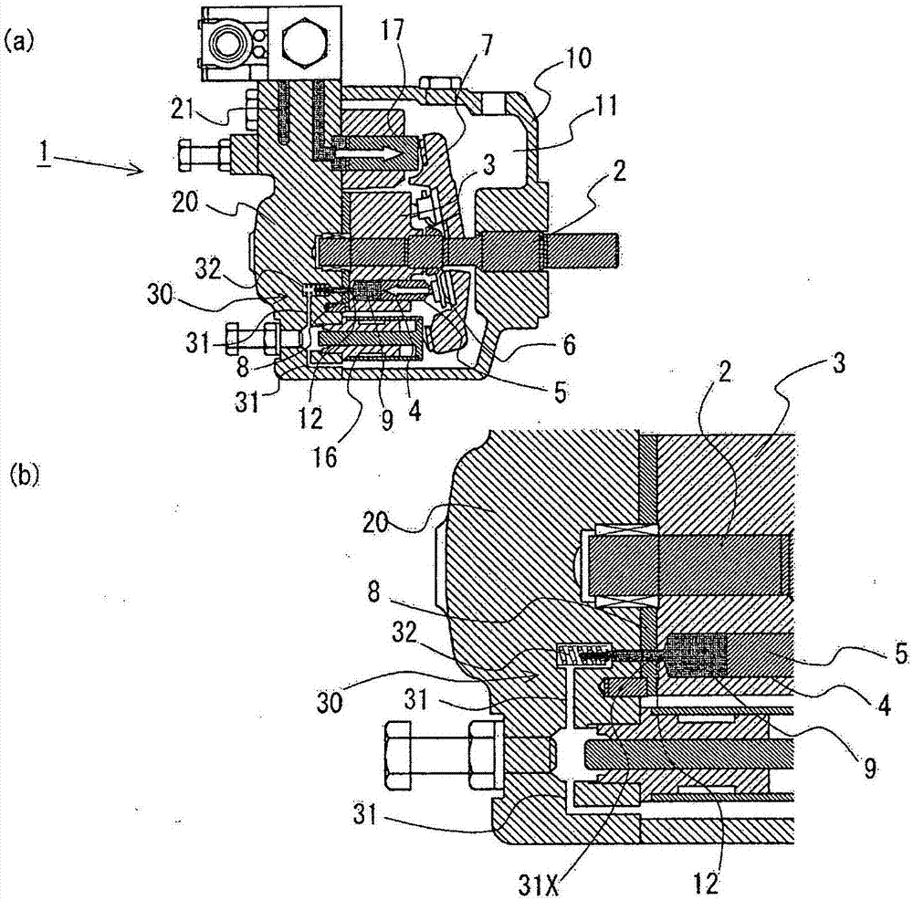
[0036] As the first embodiment of the present invention, in figure 1 The figure in the middle indicates a 2-capacity variable displacement plunger pump for rotation speed control equipped with a hydraulic circuit for avoiding abnormal pressure using a safety valve. figure 1 (a) is an overall longitudinal sectional view, and (b) is a partial sectional view showing a hydraulic circuit for avoiding abnormal pressure.

[0037] The basic configuration of the plunger pump unit other than the hydraulic circuit for avoiding abnormal pressure in the two-capacity variable plunger pump 1 for rotational speed control of this embodiment and image 3 and Figure 4 The example shown is the same.

[0038] That is, in the pump chamber 11 formed by closing the pump cover 20 of the container-shaped pump body main body 10, the rotary shaft 2 driven by the motor and the cylinder body 3 integrally rotated with the rotary shaft 2 are assembled as a single unit structure. , a plurality of bores 4...

Embodiment 2

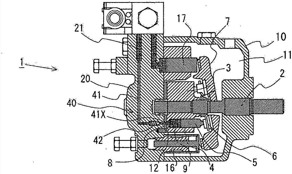
[0045] As a second embodiment of the present invention, a two-capacity variable-displacement plunger pump for speed control equipped with a hydraulic circuit for avoiding abnormal pressure using a check valve is shown in figure 2 longitudinal section view.

[0046] The basic configuration of the plunger pump unit other than the hydraulic circuit for avoiding abnormal pressure in the two-capacity variable plunger pump 1 for rotational speed control of this embodiment and figure 1 The basic configuration of the plunger pump unit of the first embodiment shown above is the same.

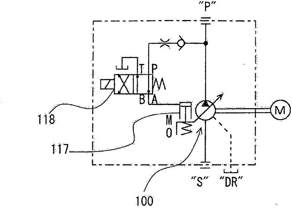
[0047] The hydraulic circuit 40 for avoiding abnormal pressure in this embodiment forms a pressure relief oil passage in the pump cover 20 that communicates the chamber 9 between the suction port and the discharge port of the flow plate 8 with the discharge oil passage 21 41. A one-way valve 42 is arranged in the pressure relief oil passage 41, at a position close to the downstream of the chamber 9. ...


PUM


Abstract

Provided is a rotational-speed-controlling variable piston pump with which it is possible to satisfactorily avoid abnormal pressures in the bore chamber of a cylinder block with a simple configuration, without causing loss of pump efficiency or increases in cost. The present invention provides a rotational-speed-controlling variable piston pump in which pistons move back and forth within a bore at a stroke suited to the angle of inclination of a swash plate along with the rotation of a cylinder block, whereby hydraulic oil is drawn into a bore chamber from an intake oil passage formed in a casing, via an intake port of a port plate against which the cylinder block slides, and the hydraulic oil is discharged to a discharge oil passage formed in the casing, via a discharge port of the port plate; wherein an abnormal-pressure-avoiding oil pressure circuit, which releases the hydraulic oil in the bore chamber out of the bore chamber when the pressure in the bore chamber positioned between the intake port and the discharge port of the port plate exceeds a predetermined pressure, is provided as being incorporated in the same unit structure within the same casing.

Description

technical field [0001] The present invention relates to, for example, a two-capacity variable plunger pump for rotational speed control, and specifically relates to a means for avoiding abnormal pressure in a chamber of a cylinder. Background technique [0002] Among the various types of hydraulic plunger pumps, for example, there is a hydraulic plunger pump that is rotationally driven by an AC servo motor and whose discharge volume can be changed by controlling its rotational speed. Quantitative hydraulic plunger pump. [0003] In addition, there is a 2-capacity variable plunger pump 100 in such a rotational speed control piston pump, and the 2-capacity variable piston pump 100 is, for example, image 3 As shown in the circuit diagram of , the electromagnetic reversing valve 118 can switch between a large capacity that sets the swash plate angle to a large inclination angle and a small capacity that sets the swash plate angle to a small inclination angle. [0004] The swas...

Claims


Application Information

Patent Timeline
Patent Type & Authority Applications(China)
IPC IPC(8): F04B1/22F04B49/10
CPCF04B1/22F04B49/10
Inventor 平出博一塚田祐也
Owner YUKEN KOGYO
Why Eureka
Try Eureka