Non-pressure storage type automatic fire extinguishing system and fire extinguishing method thereof

An automatic fire extinguishing system, non-pressure storage technology, applied in fire rescue, fire alarms, instruments, etc., can solve problems such as inability to achieve real-time monitoring, high voltage of vehicle systems, scattered distribution, etc., and achieve convenient subcontracting control Independent fire extinguishing, good sealing performance, and convenient matching installation

Inactive Publication Date: 2017-12-01
TITANICSAFETY TECH CO LTD
View PDF0 Cites 9 Cited by
  • Summary
  • Abstract
  • Description
  • Claims
  • Application Information

AI Technical Summary

Problems solved by technology

At present, the traditional domestic fire extinguishing system mainly uses dry powder, aerosol and carbon dioxide as fire extinguishing agents. Due to its poor fire extinguishing effect, inability to prevent reburning, and pollution to the environment, it cannot meet the fire extinguishing work of new energy vehicles; It is impossible to subcontract and control individual battery packs to extinguish fires; it is impossible to communicate with the on-board computer, and it is impossible to monitor in real time
However, new energy vehicles have problems such as small installation space, large number of battery packs and scattered distribution, high voltage of the vehicle system, and too many interference sources that may easily interfere with the control system.

Method used


Image

  • Non-pressure storage type automatic fire extinguishing system and fire extinguishing method thereof
  • Non-pressure storage type automatic fire extinguishing system and fire extinguishing method thereof
  • Non-pressure storage type automatic fire extinguishing system and fire extinguishing method thereof

Examples


Embodiment Construction

[0017] The technical solutions of the present invention will be clearly and completely described below in conjunction with the embodiments. Apparently, the described embodiments are only some of the embodiments of the present invention, not all of them. Based on the embodiments of the present invention, all other embodiments obtained by persons of ordinary skill in the art without creative efforts fall within the protection scope of the present invention.

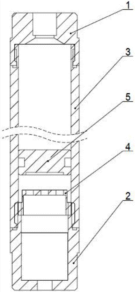
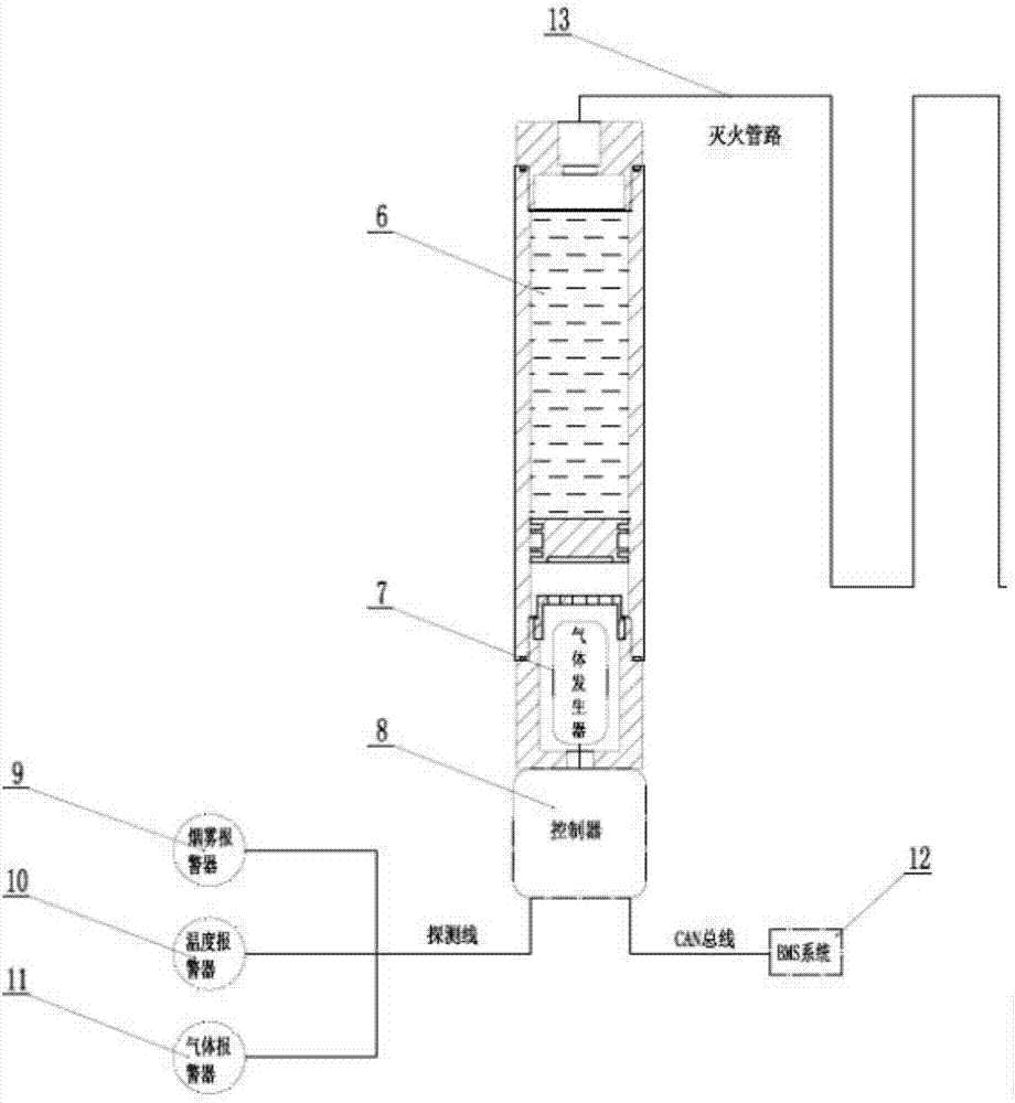
[0018] A non-pressure storage type automatic fire extinguishing system, see Figure 1-2 , including upper end cover 1, lower end cover 2, tank body 3, cover plate 4, piston 5, medicament 6, gas generator 7, controller 8, smoke alarm 9, temperature alarm 10, gas alarm 11, vehicle management System 12, fire extinguishing pipeline 13;

[0019] Specifically, an upper end cover 1 is installed on one end of the tank body 3, and a lower end cover 2 is installed on the other end; a piston 5 is movable inside the tank body 3; a cov...


PUM


Abstract

The invention discloses a non-pressure storage type automatic fire extinguishing system. The non-pressure storage type automatic fire extinguishing system comprises a tank body, a piston, a reagent, a gas generator, a controller, a vehicle-mounted management system and a fire extinguishing pipeline. An upper end cover is mounted on an end portion of the tank body while a lower end cover is mounted on the other end portion; a piston is movably arranged in the tank body; a cover plate is mounted in the tank body between the piston and the lower end cover, and a through hole is formed in the plate body of the cover plate; the gas generator is mounted in a cavity between the cover plate and the lower end cover; the reagent is accommodated in the tank body between the piston and the upper end cover; the gas generator is connected to the controller; the controller is separately connected to an alarm and the vehicle-mounted management system; and one end of the fire extinguishing pipeline hermetically penetrates through the upper end cover and communicates with the inner part of the tank body. The invention also discloses a fire extinguishing method of the non-pressure storage type automatic fire extinguishing system. The non-pressure storage type automatic fire extinguishing system disclosed by the invention is good in sealing property, convenient to match and mount, free of an external gas source to push and safer and more reliable.

Description

technical field [0001] The invention belongs to the technical field of vehicle fire protection and relates to an automatic fire extinguishing system, in particular to a non-pressure storage type automatic fire extinguishing system and a fire extinguishing method thereof. Background technique [0002] With the rapid development of my country's new energy vehicle industry, vehicle fire safety is becoming more and more important. Especially for the fire protection system in the battery compartment of the bus, more and more bus companies have begun to pay attention to it. In the future, the "vehicle fire protection system" will become a standard product for new energy vehicles. At present, the traditional domestic fire extinguishing system mainly uses dry powder, aerosol and carbon dioxide as fire extinguishing agents. Due to its poor fire extinguishing effect, inability to prevent reburning, and pollution to the environment, it cannot meet the fire extinguishing work of new ene...

Claims


Application Information

Patent Timeline
Patent Type & Authority Applications(China)
IPC IPC(8): A62C13/00A62C27/00G08B17/00
CPCA62C13/00A62C27/00G08B17/00
Inventor 冯伟光石兵纯程友丽贾磊磊张永长申喜涛
Owner TITANICSAFETY TECH CO LTD
Why Eureka
Try Eureka