I-shaped web plate for blade, mold and manufacturing method

An I-shaped, web technology, applied in the final product manufacturing, sustainable manufacturing/processing, wind turbines that are consistent with the wind direction, etc., can solve the problem of difficult to guarantee curing, affect the strength of the web bonding, and prolong the clamping time. and other problems, to achieve the effect of improving fatigue performance, improving safety, and optimizing bonding

Inactive Publication Date: 2017-12-01
BEIJING GOLDWIND SCI & CREATION WINDPOWER EQUIP CO LTD
View PDF5 Cites 6 Cited by
  • Summary
  • Abstract
  • Description
  • Claims
  • Application Information

AI Technical Summary

Problems solved by technology

There are many defects in the use of the C-shaped web. For example, there is an outer dead zone in the bonding area between the flange flange of the C-shaped web and the shell. Since the staff cannot scrape and fillet the outer dead zone, Therefore, there will be multiple stress concentration points in the outer dead zone
The stress concentration points in these bonding areas are prone to fatigue damage and failure under the action of fatigue loads. The bonding damage of wind turbine blades has a lot to do with this defect
[0003] The existing C-shaped web is directly bonded to the blade shell with an adhesive. The bonding surface of the C-shaped web consists of a main bonding surface and an auxiliary bonding surface. The main bonding surface is made of the flange edge of the web mold, but the auxiliary bonding surface At present, most of them are bonded to the web with adhesives or hand-laid with baffles. It is difficult to guarantee the accuracy of the bonding position and bonding angle, and it is difficult to guarantee the curing under the influence of the environment. Generally, it is only used for the PS surface. Bonding, and the stress of the web at the corner is relatively large, which greatly affects the strength of the web bonding
[0004] In addition, the following problems also exist in the existing C-shaped web manufacturing process: since the C-shaped web needs to be pasted for auxiliary bonding after mold closing, the mold closing time will be prolonged; because auxiliary bonding is generally done by hand lay-up Process molding method, so the working environment is worse than vacuum infusion; because hand lay-up auxiliary bonding must be operated by people, it can only be limited to SS surface and PS surface bonding in accessible areas, and hand lay-up cannot be performed in areas where people cannot enter Production of auxiliary bonding; since auxiliary bonding is a hand lay-up process, it is greatly affected by the operating environment. In the case of low winter temperatures, since there is no fixed heating device, the curing of hand lay-up auxiliary bonding is slow; Since the C-shaped web is first bonded by web, and then auxiliary bonding by hand lay-up, it is formed twice; because the auxiliary bonding adopts the hand lay-up process, the operation is more troublesome, and the production accuracy of the hand lay-up process Low, so the conformability is poor, thus prolonging the bonding operation time of the web and the shell as a whole
[0005] In addition, since the auxiliary bonding of the C-shaped web is a hand lay-up operation, the resin in the auxiliary bonding fiber cloth is inevitably excessive during the production process, so the C-shaped web formed by the hand lay-up operation will be relatively heavy.

Method used


Image

  • I-shaped web plate for blade, mold and manufacturing method
  • I-shaped web plate for blade, mold and manufacturing method
  • I-shaped web plate for blade, mold and manufacturing method

Examples


Embodiment Construction

[0027] Exemplary embodiments of the present invention will be described in detail below with reference to the accompanying drawings. Like reference numerals refer to like parts throughout the specification.

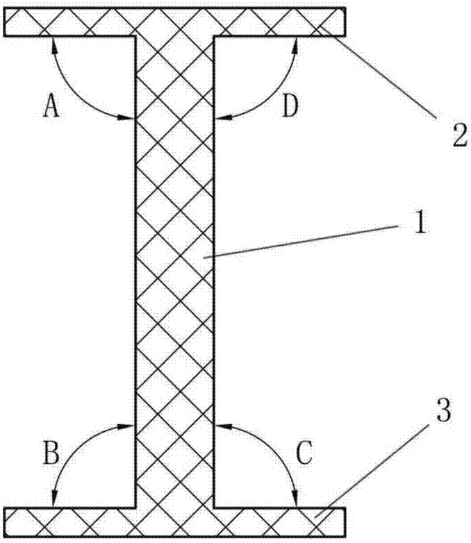
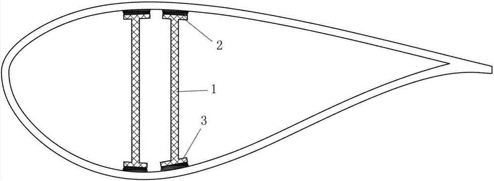
[0028] figure 2 is a cross-sectional view of an I-shaped web for a blade according to an exemplary embodiment of the present invention; image 3 is a schematic diagram of an I-shaped web installed in a blade according to an exemplary embodiment of the present invention.

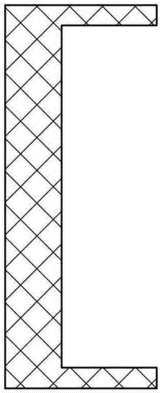
[0029] Such as figure 2 and image 3 As shown, the I-shaped web for a blade according to an exemplary embodiment of the present invention includes: a main body 1 in the shape of a strip, and the width of the main body 1 gradually decreases along the length direction from the root of the main body 1 to the tip. Small; the first rib 2 and the second rib 3 are formed on both sides of the main body 1 along the width direction of the main body 1 (for example, figure 2 The upper and lower sides of the ...


PUM


Abstract

The invention provides an I-shaped web plate for a blade, a mold and a manufacturing method. The I-shaped web plate for the blade comprises a main body, a first baffle edge and a second baffle edge, wherein the main body is in a long-striped plate shape; the width of the main body is gradually reduced in a length direction from the root part to the point part of the main body; and the first baffle edge and the second baffle edge are formed at the two sides of the main body in the width direction of the main body so as to form an I shape with the main body. The I-shaped web plate provided by the invention has the advantages that the force bearing is balanced and uniform; and no bonding dead corner with a casing exists, and the like.

Description

technical field [0001] The invention relates to the field of wind power generation, in particular to a blade I-shaped web, a mold and a manufacturing method. Background technique [0002] At present, the blades of wind turbines use C-shaped webs, such as figure 1 shown. There are many defects in the use of the C-shaped web. For example, there is an outer dead zone in the bonding area between the flange flange of the C-shaped web and the shell. Since the staff cannot scrape and fillet the outer dead zone, Therefore, there will be multiple stress concentration points in the outer dead zone. The stress concentration points in these bonding areas are prone to fatigue damage and failure under the action of fatigue load, and the bonding damage of wind turbine blades has a great relationship with this defect. [0003] The existing C-shaped web is directly bonded to the blade shell with an adhesive. The bonding surface of the C-shaped web consists of a main bonding surface and an...

Claims


Application Information

Patent Timeline
Patent Type & Authority Applications(China)
IPC IPC(8): B29C70/36B29C70/54B29C33/42F03D1/06
CPCB29C33/42B29C70/36B29C70/54F03D1/0675Y02E10/72Y02P70/50
Inventor 郑永俐赵其光吴志全
Owner BEIJING GOLDWIND SCI & CREATION WINDPOWER EQUIP CO LTD
Why Eureka
Try Eureka