Pipe fitting pinching mechanism

A pipe clamping and pipe clamping technology, which is applied in the direction of conveyors, conveyor objects, transportation and packaging, etc., can solve the problems of low work efficiency, pipe damage, low pipe adjustment efficiency, etc., and achieve the effect of reasonable structural design and stable swing

Inactive Publication Date: 2017-12-01
浙江绿康农产品配送有限公司
View PDF15 Cites 23 Cited by
  • Summary
  • Abstract
  • Description
  • Claims
  • Application Information

AI Technical Summary

Problems solved by technology

[0002] Pipe fittings are parts that connect pipes into pipelines. Pipe fittings are parts that play the roles of connection, control, direction change, diversion, sealing and support in the pipeline system. Pipe fittings, threaded pipe fittings, flanged pipe fittings and welded pipe fittings. During the production and processing of pipe fittings, the pipe fittings need to be cut, flared, punched and bent according to the needs of use. Therefore, when the pipe fittings are carried out in sequence. The pipe fittings need to be transported smoothly among the processing equipment in each process in sequence according to the processing needs. The common method of pipe fitting translation transportation is to use manual picking and placing of the pipe fittings. The work intensity of the workers is high and the work efficiency is low. And due to the randomness of manual operation, the pipe fittings will often be dropped during the process of picking and placing the pipe fittings, resulting in damage to the pipe fittings. The existing common method is to use the mechanical arm to pick and place the pipe fittings between the various processes. The mechanism is complex, and the translation efficiency of pipe fittings is low. It is difficult to continuously translate and transport the pipe fittings that have completed the production and processing steps in the previous process. The pipe fittings can be rotated to adjust the horizontal position of the pipe fittings. It is necessary to use the rotating mechanism to adjust the pipe fittings after the pipe fittings are translated to the designated position. Large errors affect the normal processing of pipe fittings and cannot meet the needs of production and use

Method used


Image

  • Pipe fitting pinching mechanism
  • Pipe fitting pinching mechanism
  • Pipe fitting pinching mechanism

Examples


Embodiment Construction

[0012] In order to further describe the present invention, a specific implementation of a pipe pinch mechanism will be further described below in conjunction with the accompanying drawings. The following examples are explanations of the present invention and the present invention is not limited to the following examples.

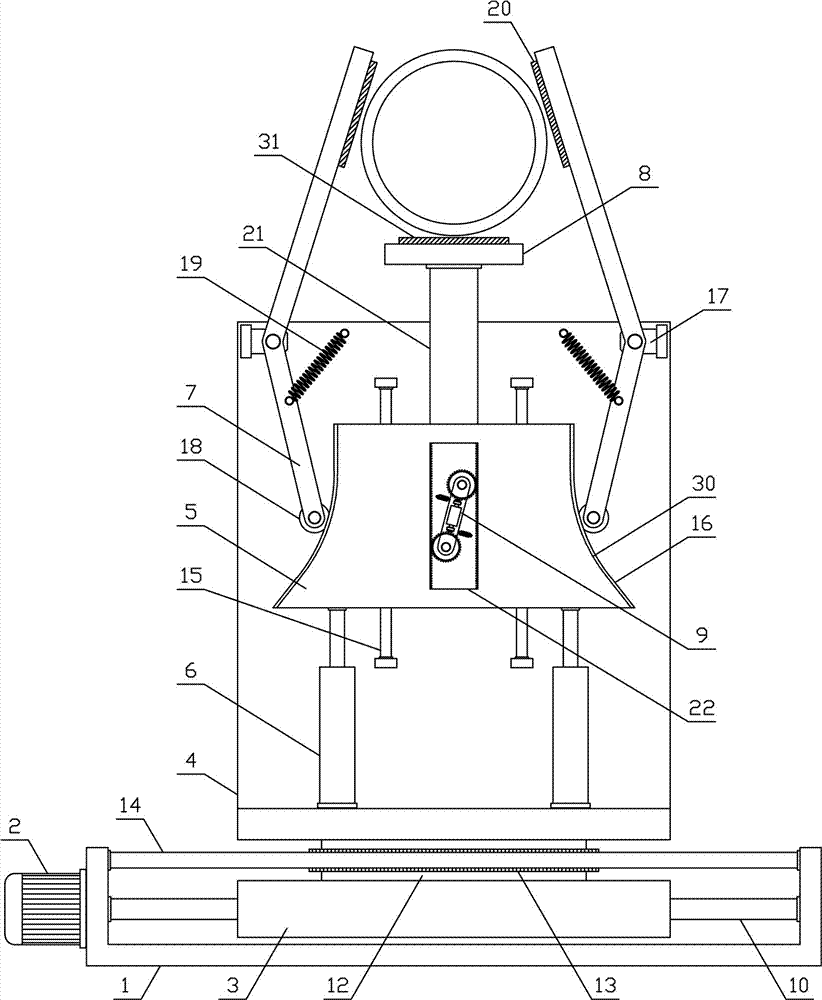
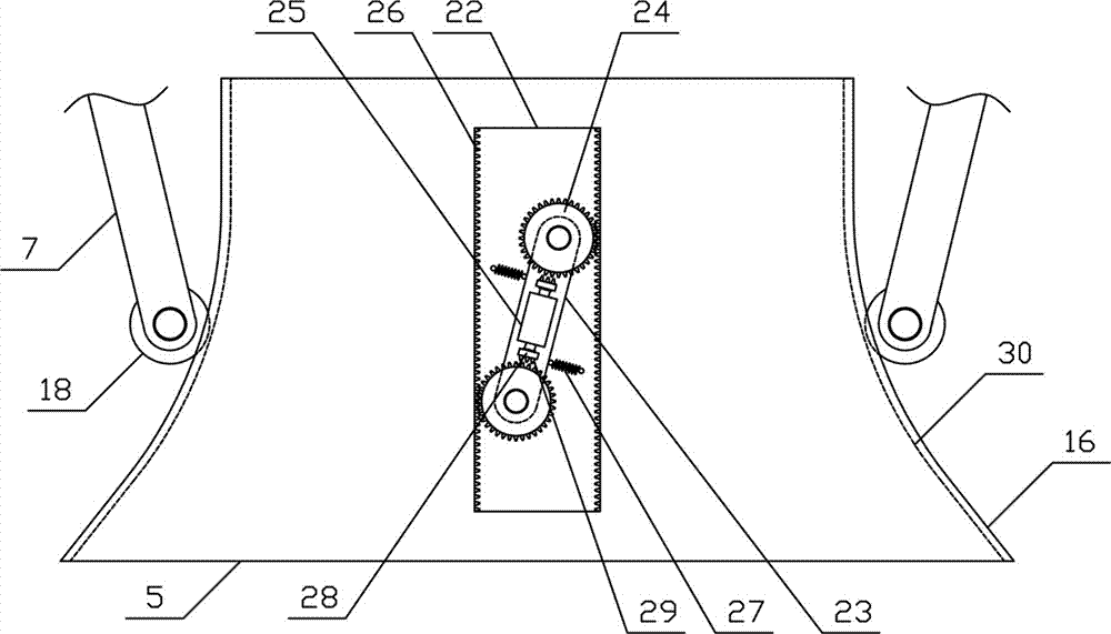
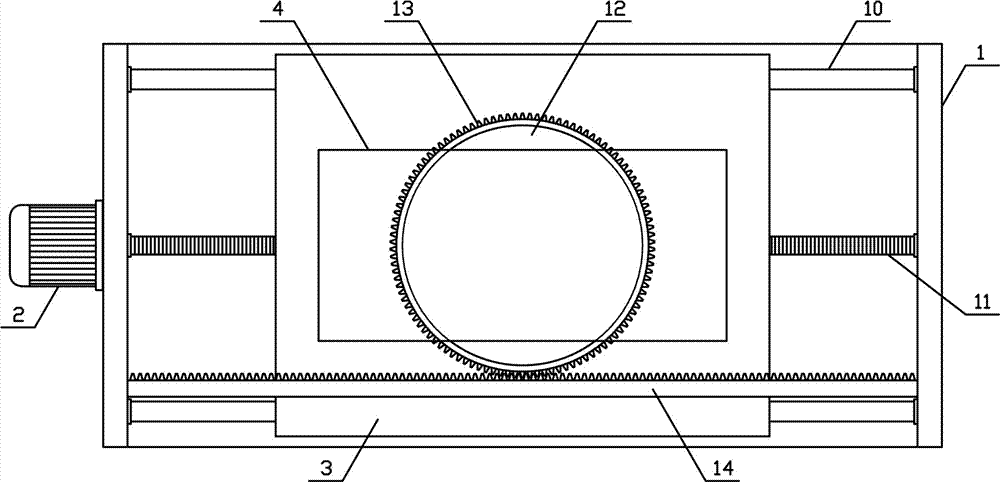
[0013] like figure 1 , image 3 As shown, a pipe fitting pinching mechanism of the present invention includes a translation base 1, a translation motor 2, a translation support 3, a clamping support 4, a lifting push plate 5, a lifting cylinder 6, a clamping plate 7, a bearing plate 8 and a card Plate mechanism 9, translation guide rods 10 are horizontally and symmetrically arranged on both sides of the upper side of the translation base 1 of the present invention, the translation support 3 is slidingly arranged on the translation guide rods 10 in the horizontal direction, and the upper middle part of the translation base 1 is horizontally connected with a t...


PUM


Abstract

The invention discloses a pipe fitting pinching mechanism, and belongs to the field of pipe machining conveyance mechanical equipment. The pipe fitting pinching mechanism comprises a translation base, a translation motor, a translation support, a pipe clamping support, a lifting push plate, lifting air cylinders, pipe clamping plates, a pipe bearing plate and a plate clamping mechanism. The translation support is arranged on translation guide rods in a sliding mode in the horizontal direction. The pipe clamping support is vertically arranged at the upper side of a fixed rotating shaft. The lifting push plate is arranged on lifting guide rods in a sliding mode in the vertical direction. Arc-shaped plate push surfaces are symmetrically arranged at the two sides of the lifting push plate correspondingly. The pipe clamping plates are symmetrically arranged at the two sides of the pipe clamping support separately. The pipe bearing plate is horizontally arranged at the upper side of a pipe bearing supporting rod. The plate clamping mechanism is arranged on the pipe clamping support and located at one side of a lifting clamping groove. The pipe fitting pinching mechanism is reasonable in structural design, pipe fittings of various sizes and dimensions can be clamped and fixed firmly, the pipe fittings can be stably rotated and adjusted synchronously in the translation process of the pipe fittings, and the production and use needs are met.

Description

technical field [0001] The invention belongs to the field of pipe material processing and conveying machinery, and in particular relates to a pipe fitting pinching mechanism. Background technique [0002] Pipe fittings are parts that connect pipes into pipelines. Pipe fittings are parts that play the roles of connection, control, direction change, diversion, sealing and support in the pipeline system. Pipe fittings, threaded pipe fittings, flanged pipe fittings and welded pipe fittings. During the production and processing of pipe fittings, the pipe fittings need to be cut, flared, punched and bent according to the needs of use. Therefore, when the pipe fittings are carried out in sequence. The pipe fittings need to be transported smoothly among the processing equipment in each process in sequence according to the processing needs. The common method of pipe fitting translation transportation is to use manual picking and placing of the pipe fittings. The work intensity of the...

Claims


Application Information

Patent Timeline
Patent Type & Authority Applications(China)
IPC IPC(8): B65G47/90
CPCB65G47/901B65G2201/0276
Inventor 张帼威
Owner 浙江绿康农产品配送有限公司
Why Eureka
Try Eureka