Automatic distribution mechanism for stock bins

A material distributing mechanism and silo technology, which is applied in the direction of conveyors, conveyor objects, conveyor control devices, etc., can solve problems such as affecting the efficiency of feeding automation, vibration of materials in the tray, and large vibration of the tray, etc. Achieve the effect of simple structure, good rotation consistency and good stability

Inactive Publication Date: 2017-12-01
青岛英泰奥通智能科技有限公司
View PDF6 Cites 8 Cited by
  • Summary
  • Abstract
  • Description
  • Claims
  • Application Information

AI Technical Summary

Problems solved by technology

[0002] When the injection molding machine is injection molding, it is often necessary to embed inserts to improve product performance. During the continuous feeding process of inserts, silo equipment is needed. Inserts are generally placed in the tray, and then the stacked trays are placed in the bin. , when the trays are automatically loaded in the silo, the continuity, stability and automation of the silo equipment are very important, especially when the stacked trays are divided in the silo, if the trays are unstable, set the The inserts in the tray will vibrate out during the tray separation proc

Method used


Image

  • Automatic distribution mechanism for stock bins
  • Automatic distribution mechanism for stock bins
  • Automatic distribution mechanism for stock bins

Examples


Embodiment Construction

[0017] Referring to the accompanying drawings, a description will be given in detail of a silo automatic distributing mechanism of the present invention.

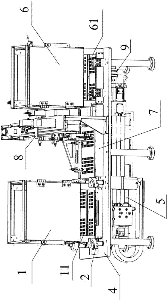
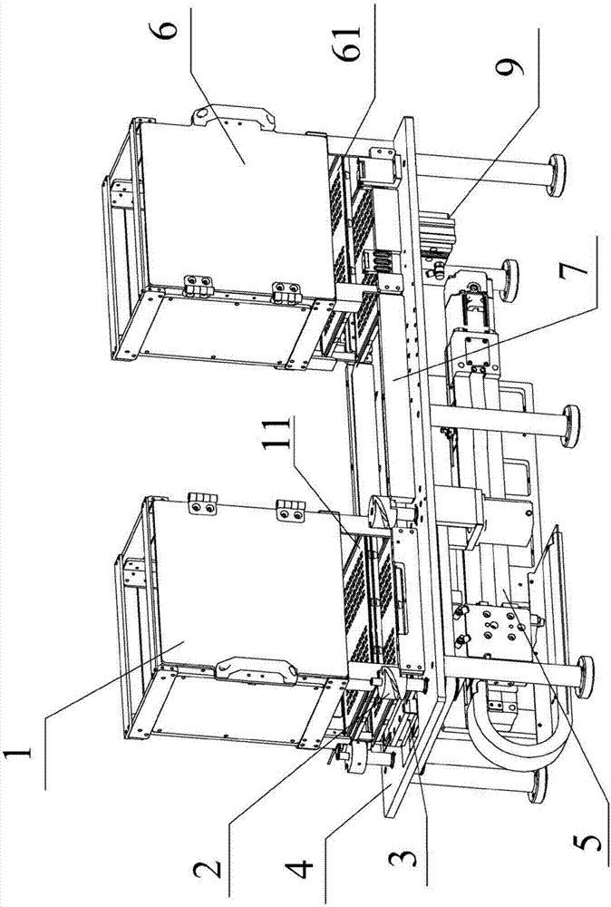
[0018] like figure 1 , figure 2 As shown, a bin automatic distributing mechanism includes a full-pan bin 1 for stacking insert trays 11, a bottom part of the full-pan bin 1 for making the insert tray 11 Separated from the full tray silo 1 separating device 2 and the tray positioner 3 for positioning the detached insert tray 11; also includes a unit located at the bottom of the base 4 supporting the full tray 1 Axis robot 5 and an empty tray bin 6 for storing empty trays 61 located on the other side of the base 4 top; The track 7 for transporting the insert tray 11 and the empty tray 61 and the handling device 8 located on one side of the track 7 for insert picking the insert tray 11; The lower part of the empty tray storage bin 6 is installed on the lifting cylinder 9 on the base 4 .

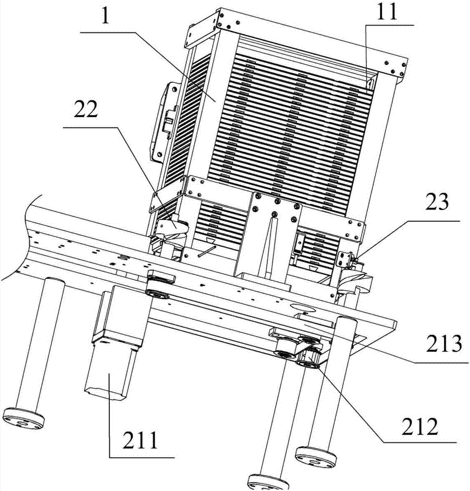
[0019] like image 3 , Figure ...


PUM


Abstract

The invention relates to the field of automatic mechanical equipment, in particular to an automatic distribution mechanism for stock bins. The automatic distribution mechanism for the stock bins comprises the full tray stock bin, a tray distribution device and tray positoiners, wherein insert trays are stacked in the full tray stock bin, and the tray distribution device and the tray positoiners are mounted on the lower portion of the full tray stock bin. The automatic distribution mechanism for the stock bins further comprises a single-axis robot located on the lower portion of a base used for supporting the full tray stock bin and the empty tray stock bin located on the other side of the upper portion of the base. The automatic distribution mechanism for the stock bins further comprises a conveying track located between the full tray stock bin and the empty tray stock bin and a transferring device located on one side of the track. The automatic distribution mechanism for the stock bins further comprises a jacking cylinder which is located on the lower portion of the empty tray stock bin and mounted on the base. The automatic distribution mechanism for the stock bins is simple in overall structure, ingenious in design, stable in tray distribution and good in continuity; the tray distribution device is formed by simply combining a shifting wheel with a transmission device, a conventional tray distribution device internally provided with a cylinder for tray distribution and provided with an assembly comprising complex structures such as a separation cylinder, a jacking cylinder and a lifting cylinder is replaced, and the problems that the speeds of the cylinders are inconsistent, tray distribution vibration is large, and consequentially materials in trays are prone to being vibrated out are solved; and the automatic distribution mechanism for the stock bins has potential market value.

Description

technical field [0001] The invention relates to the field of automatic mechanical equipment, in particular to an automatic material distribution mechanism for a silo. Background technique [0002] When the injection molding machine is injection molding, it is often necessary to embed inserts to improve product performance. During the continuous feeding process of inserts, silo equipment is needed. Inserts are generally placed in the tray, and then the stacked trays are placed in the bin. , when the trays are automatically loaded in the silo, the continuity, stability and automation of the silo equipment are very important, especially when the stacked trays are divided in the silo, if the trays are unstable, set the The inserts in the tray will vibrate out during the tray separation process, affecting the automation efficiency of feeding and delaying production. However, the current conventional tray separation device is mainly composed of cylinders. The components include se...

Claims


Application Information

Patent Timeline
IPC IPC(8): B65G59/06B65G47/82B65G43/08B65G57/30
CPCB65G59/067B65G43/08B65G47/82B65G57/301B65G2201/0258
Inventor 刘光富
Owner 青岛英泰奥通智能科技有限公司
Why Eureka
Try Eureka