
Velocity composition based non-force-fighting differential mechanism

A technology of speed synthesis and differential, which is applied in the direction of differential transmission, transmission parts, belts/chains/gears, etc. It can solve the problems of large moment of inertia, high control accuracy of dispute control unit, and very high requirements, and achieve low inertia , avoidance force dispute phenomenon, small size effect

Active Publication Date: 2017-12-01
BEIJING AUTOMATION CONTROL EQUIP INST
View PDF4 Cites 1 Cited by
  • Summary
  • Abstract
  • Description
  • Claims
  • Application Information

AI Technical Summary

Problems solved by technology

[0004] The technical problem to be solved in the present invention is: the existing differential that solves the phenomenon of power disputes and fault isolation of double-redundant electromechanical actuators will bring very high requirements for the control accuracy of the control unit, or have high requirements for machining accuracy and assembly accuracy The requirements are very high and the moment of inertia is large

Method used


Image

  • Velocity composition based non-force-fighting differential mechanism

Examples


Embodiment Construction

[0026] A power-dispute-free differential based on speed synthesis of the present invention will be described in detail below with reference to the drawings and embodiments.

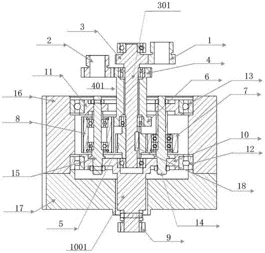
[0027] Such as figure 1 As shown, the differential of the present invention mainly includes a first input gear 1, a second input gear 2, a first coaxial gear 3, a second coaxial gear 4, a small sun gear 5, a large sun gear 6, and short planetary gears 7. Long planetary gear 8, output gear 9, planetary carrier 10, cage 11, planetary carrier support bearing 12, cage support bearing 13, short planetary wheel pillar 14, long planetary wheel pillar 15, supporting shell 16 and shell end cap 17.

[0028] Wherein, the first input gear 1 is used for inputting rotation, and the first input gear 1 meshes with the first coaxial gear 3 . The first coaxial gear 3 and the small sun gear 5 are coaxial, and the two are respectively fixedly installed on the two ends of the first transmission shaft 301, so that the first ...


PUM


Abstract

The invention belongs to the technical field of electromechanical actuators, and particularly relates to a velocity composition based non-force-fighting differential mechanism. The differential mechanism mainly comprises a first input gear, a second input gear, a first coaxial gear, a second coaxial gear, a small sun wheel, a big sun wheel, a short planet wheel, a long planet wheel, an output gear, a planet carrier, a holding frame, a planet carrier supporting bearing, a holding frame supporting bearing, a short planet wheel supporting post, a long planet wheel supporting post, a supporting housing and a housing end cover. The velocity composition based non-force-fighting differential mechanism solves the problem that control precision requirements on a control unit are very high or processing precision requirements and assembly precision requirements are very high as an existing differential mechanism has a dual-redundancy electromechanical actuator force-fighting phenomenon isolated from faults, and rotational inertia is great; a single-row planetary gear and a double-row planetary gear are combined for transmission, so that a non-force-fighting differential mechanism for dual-channel input speed synthesis is realized; and the differential mechanism is small in size and is low inertia.

Description

technical field [0001] The invention belongs to the technical field of electromechanical actuators, and in particular relates to a powerless dispute differential based on speed synthesis. Background technique [0002] The dual-redundancy electric rudder system is widely used in the UAV control system to improve the reliability of UAV missions. At present, a key technology facing the development of dual-redundant electric steering system is how to solve the problem of force dispute and fault isolation caused by the output motion synthesis of dual motors. The usual solutions of relevant research institutes at home and abroad are the clutch control scheme through torque synthesis and the differential epicyclic gear train control scheme through mechanical motion synthesis. The former needs to solve the phenomenon of load balancing and force disputes, and because the motion synthesis is a mechanically rigid structure, the control accuracy of the control unit is required to be ve...

Claims


Application Information

Patent Timeline
IPC IPC(8): F16H48/06F16H57/021F16H57/023F16H57/08
Inventor 王怀王连丛卢扬王瑛琦那学智熊官送海克飞
Owner BEIJING AUTOMATION CONTROL EQUIP INST
Features
  • Generate Ideas
  • Intellectual Property
  • Life Sciences
  • Materials
  • Tech Scout
  • Unparalleled Data Quality
  • Higher Quality Content
  • 60% Fewer Hallucinations
Learn More