
Method for measuring complex solution components by multi-position modulation of transmission and fluorescence excitation light sources

A fluorescence excitation, multi-position technology, used in fluorescence/phosphorescence, material excitation analysis, measurement devices, etc., can solve the problems of unsatisfactory chemical inspection methods, inability to respond well, poor pertinence, etc., and achieve pollution-free high-precision measurement. , the effect of suppressing nonlinear problems and increasing the amount of information

Inactive Publication Date: 2017-12-01
TIANJIN UNIV
View PDF3 Cites 0 Cited by
  • Summary
  • Abstract
  • Description
  • Claims
  • Application Information

AI Technical Summary

Problems solved by technology

[0002] In the existing technology, the relatively mature technology is to detect the content of the target components measured in the bagged complex solution through chemical inspection, which has the outstanding advantage of high accuracy, but the method of chemical inspection cannot meet the requirements of fast, non-contact, and Due to its non-contact and non-polluting characteristics, it is also possible to realize the content detection of the target components measured in the complex solution in the packaging bag due to the requirement of no pollution.
[0003] In view of the complexity of complex solution components, pure transmission spectrum can obtain the information of all complex solution components, which is poor in pertinence
In order to further improve the measurement accuracy of the target components measured in complex solutions, combined with the strong pertinence of fluorescence, but due to the strong scattering of complex solutions and other factors that cause spectral nonlinearity and the influence of spectral background noise, it cannot respond well to the measured characteristics of matter

Method used


Image

  • Method for measuring complex solution components by multi-position modulation of transmission and fluorescence excitation light sources
  • Method for measuring complex solution components by multi-position modulation of transmission and fluorescence excitation light sources
  • Method for measuring complex solution components by multi-position modulation of transmission and fluorescence excitation light sources

Examples


Embodiment 1

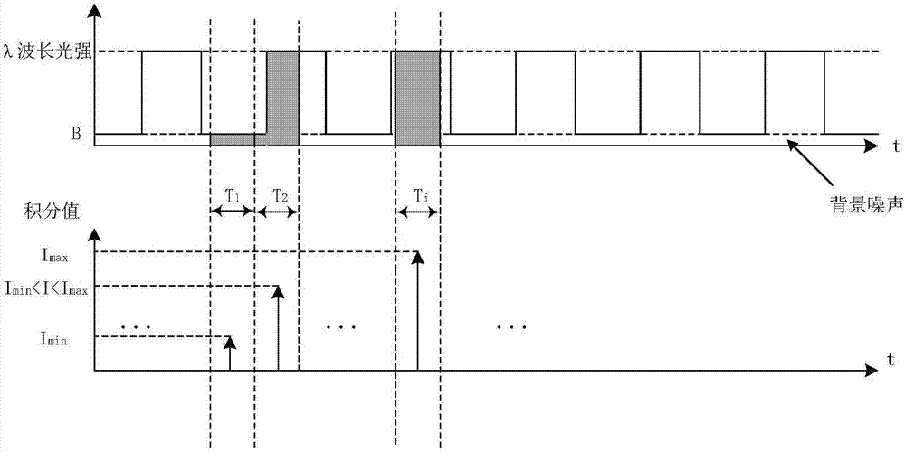
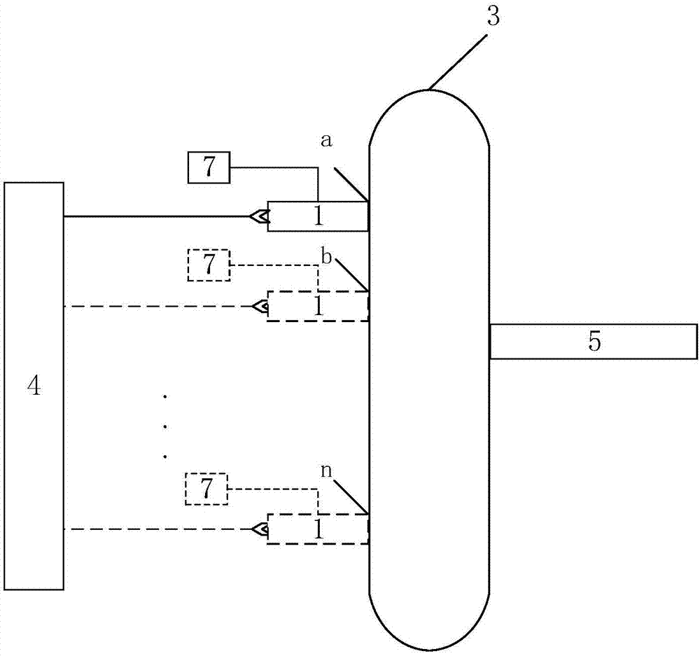
[0054] The embodiment of the present invention provides a multi-position modulation transmission and fluorescence excitation light source method for measuring complex solution components, the devices used are such as figure 2 As shown, it includes: a light source 1 , a packaging bag 3 , a displacement platform 4 , a spectrum receiving device 5 and a modulation device 7 .

[0055] Wherein, ensure that the light output port of the light source 1 and the incident slit of the spectrum receiving device 5 are close to the packaging bag 3, the modulation device 7 modulates the light source 1 so that it sends out a square wave optical signal, and the light source 1 faces the inside of the packaging bag 3 at the first position a. The bagged complex solution is transmitted and excited, and the transmission spectrum and fluorescence spectrum are collected by the spectrum receiving device 5; the light source is controlled by the displacement platform 4 to move to the second position b, an...

Embodiment 2

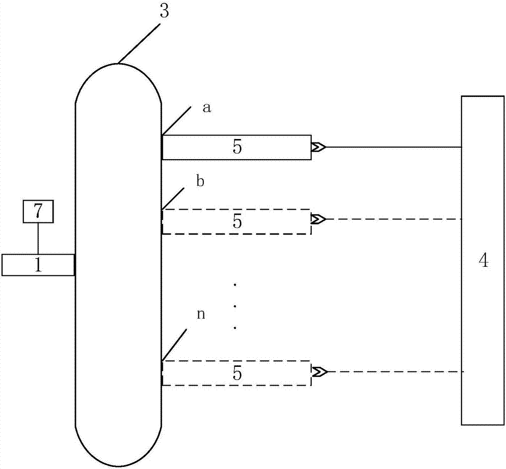
[0064] The difference between the embodiment of the present invention and embodiment 1 is only that the light source 3 and the movement mode of the spectrum receiving device 7 are different, see the following description for details:

[0065] see image 3 To ensure that the light outlet of the light source 1 and the incident slit of the spectrum receiving device 5 are close to the packaging bag 3, the modulation device 7 modulates the light source 1 so that it sends out a square wave light signal, and the light source 1 transmits and excites the bagged complex solution in the packaging bag 3 , the transmission spectrum and the fluorescence spectrum are collected by the spectrum receiving device 5 . Control the spectrum receiving device 7 to move to the second position b through the displacement platform 6, collect the transmission spectrum and fluorescence spectrum at this position, then control the spectrum receiving device 7 to move to position n through the displacement pla...

Embodiment 3

[0070] During specific implementation, due to the limitation of the space structure, it may occur that the light source 1 and the spectrum receiving device 5 cannot be close to the packaging bag 3. At this time, an optical fiber can be respectively arranged at the light source 1 and the spectrum receiving device 5 as the incident optical fiber 2 and outgoing fiber 6.

[0071] see Figure 4 , the modulation device 7 modulates the light source 1 to make it emit a square-wave optical signal, the light source 1 transmits and excites the bagged complex solution in the packaging bag 3 through the incident optical fiber 2, and the spectrum receiving device 5 collects the transmission spectrum and the fluorescence spectrum through the outgoing optical fiber 6 , the incident optical fiber 2 and the outgoing optical fiber 6 are respectively close to the packaging bag 3, the position a is the first position of the incident optical fiber 2, and the spectrum receiving device 5 collects the...


PUM


Abstract

The invention discloses a method for measuring complex solution components by multi-position modulation of transmission and fluorescence excitation light sources. According to the method, the light sources are modulated by a modulation device and include a transmission light source and a fluorescence excitation light source, complex solution is transmitted by the transmission light source and excited by the fluorescence excitation light source, a displacement platform controls the transmission light source and the fluorescence excitation light source to move to a plurality of positions, so that the complex solution is transmitted and excited, transmission spectrums and fluorescence spectrums are acquired by a spectrum receiving device, the time sequence of each wavelength in the transmission spectrums and the fluorescence spectrums acquired at a plurality of positions is transformed to a frequency domain, transmission spectrums in the frequency domain and fluorescence spectrums in the frequency domain are constructed by the aid of fundamental components with various wavelengths, so that a mathematical model is built according to chemical examination data after normalization processing, and transmission spectrums in frequency domains and fluorescence spectrums in frequency domains at a plurality of positions of unknown complex solution are acquired by the same method and substituted into the mathematical model after normalization to obtain the content of measured target components.

Description

technical field [0001] The invention relates to the field of concentration analysis stoichiometry of spectral complex solutions, in particular to a method for measuring components of complex solutions in combination with multi-position modulation transmission and fluorescence excitation light sources. Background technique [0002] In the existing technology, the relatively mature technology is to detect the content of the target components measured in the bagged complex solution through chemical inspection, which has the outstanding advantage of high accuracy, but the method of chemical inspection cannot meet the requirements of fast, non-contact, and Due to its non-contact and non-polluting characteristics, it is also possible to realize the content detection of the target components measured in the complex solution in the packaging bag due to the non-pollution requirement. [0003] In view of the complexity of complex solution components, pure transmission spectrum can obt...

Claims


Application Information

Patent Timeline
Patent Type & Authority Applications(China)
IPC IPC(8): G01N21/64
CPCG01N21/64G01N2021/6491
Inventor 李刚张梦秋张盛昭罗永顺林凌
Owner TIANJIN UNIV
Learn More