
A Planar Wide Stop-Band Dual-Band Filter

A wide stopband and filter technology, applied in the field of planar microstrip filters, can solve problems such as general stopband characteristics, and achieve the effect of wide stopband, simple design, and small size

Inactive Publication Date: 2019-12-10
SOUTH CHINA UNIV OF TECH
View PDF2 Cites 0 Cited by
  • Summary
  • Abstract
  • Description
  • Claims
  • Application Information

AI Technical Summary

Problems solved by technology

The patent uses coupled microstrip lines and stubs to achieve dual-frequency effect; uses adjustable capacitors to realize independent adjustment of the two frequency bands of the dual-frequency filter; the circuit structure is compact and simple; better isolation effect is obtained in the dual-frequency band, and the smaller insertion loss; but the stopband characteristics are average

Method used


Image

  • A Planar Wide Stop-Band Dual-Band Filter
  • A Planar Wide Stop-Band Dual-Band Filter
  • A Planar Wide Stop-Band Dual-Band Filter

Examples


Embodiment

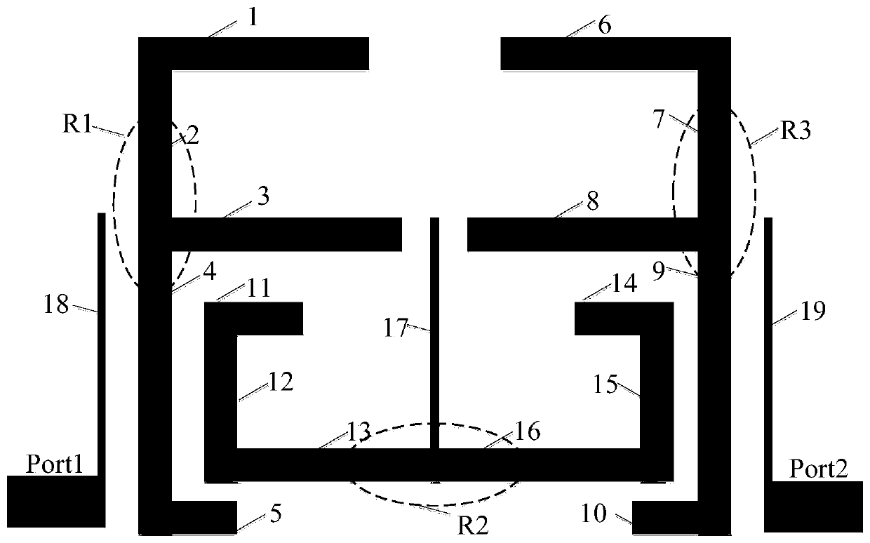
[0032] The structure of the planar wide stopband dual-frequency filter disclosed in this embodiment is as follows: image 3 As shown, it is fabricated on a double-sided copper-clad microstrip board in the form of a printed circuit board, and the other side of the microstrip board is a copper-clad ground plane. The microstrip line is made on one side of the double-sided copper-clad board, and there are respectively feeder ports port1 and port2 for inputting or outputting electromagnetic wave signals, a first resonator R1, a second resonator R2, and a third resonator R3. Each resonator is a stub-loaded resonator, consisting of a half-wavelength resonator and a loaded open-circuit stub.

[0033] Wherein, the feeder port port1, the feeder port port2, the first resonator R1, the second resonator R2, and the third resonator R3 are located on the same horizontal line.

[0034] The feeder port port1 is vertically connected to the first port feeder 18 for feeding in or out electromagn...


PUM


Abstract

The present invention discloses a planar wide stopband double-frequency filter, which is fabricated on a dielectric substrate in the manner of a printed circuit board. On the same surface of the dielectric substrate, the following elements are formed respectively: a feeder port (port1) and a feeder port (port2) for inputting or outputting the electromagnetic wave signals, a first port feeder, a second port feeder, a first resonator R1, a second resonator R2, and a third resonator R3. All the resonators are located between the first port feeder and the second port feeder; the first resonator R1 and the third resonators R3 are of the same structure and of the same impedance at every part and are placed mirror-like with respect to the second resonator R2. The resonators are all stub-loading resonators and each consists of a half-wavelength resonator and a loading open stub respectively. Through the adopting of two different resonators to obtain the double-frequency filter, the invention uses symmetrical stub-loading resonators to realize double-frequency characteristics and overcomes the interference of harmonic waves and clutter signals to obtain a relatively wide stopband.

Description

technical field [0001] The invention relates to the technical field of planar microstrip filters, in particular to a planar wide-stop-band dual-frequency filter based on stub-loaded resonators. Background technique [0002] With the rapid development of wireless communication technology, the division between frequency bands is getting finer and finer, so the interference between communication frequency bands is becoming more and more serious, so the performance of the bandpass filter determines the working quality of the communication system. The band-pass filter refers to allowing waves of a specific frequency band to pass through while shielding other frequency bands. It mainly works at the front stage of the signal transmitting end and the rear stage of the signal receiving end to suppress harmonic and clutter signals and ensure the desired signal. pure. At present, there are mainly researches on single-frequency filter and double-frequency filter in the bandpass filter....

Claims


Application Information

Patent Timeline
Patent Type & Authority Patents(China)
IPC IPC(8): H01P1/212
CPCH01P1/212
Inventor 陈付昌谢雅李钊
Owner SOUTH CHINA UNIV OF TECH
Learn More