
A visual real-time monitoring method of optical fiber connection in smart substation

A technology of intelligent substation and optical fiber connection, which is applied in the direction of electrical components, circuit devices, information technology support systems, etc., to achieve the effect of convenient fault diagnosis and maintenance

Active Publication Date: 2019-10-15
HONGHE POWER SUPPLY BUREAU OF YUNNAN POWER GRID
View PDF5 Cites 0 Cited by
  • Summary
  • Abstract
  • Description
  • Claims
  • Application Information

AI Technical Summary

Problems solved by technology

In engineering practice, it is often necessary to know which optical fibers a certain signal flow passes through or which signal flow is carried by a certain optical fiber, and the instant on-off status or abnormal status of the optical fiber. Currently, there is no way to visually display this information

Method used


Image

  • A visual real-time monitoring method of optical fiber connection in smart substation
  • A visual real-time monitoring method of optical fiber connection in smart substation

Examples


Embodiment 1

[0051] In order to make it easier for those skilled in the art to understand and implement the present invention, the present invention will be further described in detail below in conjunction with the accompanying drawings and specific embodiments.

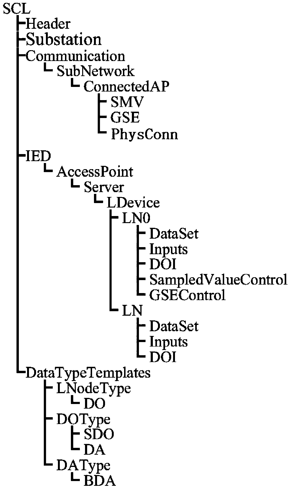
[0052] figure 1 It is a tree structure diagram of the SCD file of a smart substation. The SCD file mainly includes five parts: Header, Substation, Communication, IED, and DataTypeTemplate. Communication and IED are two parts related to optical fiber connection. The Communication section describes the communication parameter configuration of each IED; each IED represents an intelligent electronic device (such as a relay protection device, a measurement and control device, etc.) Nodes and data objects, and communication services that devices can provide.

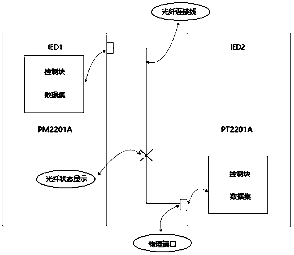
[0053] figure 2 It is a schematic diagram of the relationship between the optical fiber connection between two IEDs. Optical fiber connection refers to the communication conn...


PUM


Abstract

The invention discloses a visual real-time monitoring method for optical fiber connection in an intelligent substation. The method comprises the following steps: analyzing an SCD file; constructing optical fiber connection wires among physical ports of IEDs; constructing an optical fiber association table; acquiring a GOOSE / SV link alarm status of receiver IEDs in a real-time manner, and acquiring a light intensity lower limit exceeding alarm status of sender IEDs in a real-time manner; carrying out judgments on an optical fiber link status; and drawing an optical fiber connection diagram. The method provided by the invention has the advantages that connection matching and drawing of optical fiber connection relations can be automatically carried out through information of the IED equipment in the SCD file, and matching of optical fiber status information is carried out at the same time, so that optical connections among the IED equipment, information sending and receiving conditions of the connections and connection statuses can be visually displayed to a user; and failure diagnosis and maintenance carried out by onsite technicians can be facilitated.

Description

technical field [0001] The invention relates to an intelligent substation SCD file visualization technology, in particular to a visual real-time monitoring method for an optical fiber connection of an intelligent substation. Background technique [0002] At present, the construction of a new generation of smart substations in my country is in full swing, and the most important thing in smart substations is the use of digital methods to build communication network systems for secondary equipment. Series of standards and other standards derived from this series of standards. DL 860 stipulates an SCL file to describe the configuration of the substation. The SCL file is divided into 4 categories, namely the SSD file describing the substation specification, the ICD file describing the IED capability, the SCD file describing the complete configuration of the whole station, and the CID describing the configuration of a single IED. document. figure 2 It clearly shows the positions ...

Claims


Application Information

Patent Timeline
Patent Type & Authority Patents(China)
IPC IPC(8): H02J13/00
CPCH02J13/00019Y02E60/00Y04S10/16Y04S10/18
Inventor 李远甄家林范祺张炳旺黄文秀周坤
Owner HONGHE POWER SUPPLY BUREAU OF YUNNAN POWER GRID
Learn More