Gripping manipulator

A technology of grasping manipulators and driving mechanisms, applied in manipulators, chucks, manufacturing tools, etc., can solve problems such as speed loss and unstable operation speed, and achieve the effect of reducing speed loss, simple structure, and good motion neutrality.

Inactive Publication Date: 2017-12-05
LUOYANG INST OF SCI & TECH
View PDF15 Cites 5 Cited by
  • Summary
  • Abstract
  • Description
  • Claims
  • Application Information

AI Technical Summary

Problems solved by technology

[0003] The purpose of the present invention is to provide a low-cost grasping manipulator that can effectively solve the problems of unstable operating speed and speed loss in the manipulator in the prior art.

Method used


Image

  • Gripping manipulator
  • Gripping manipulator

Examples


Embodiment Construction

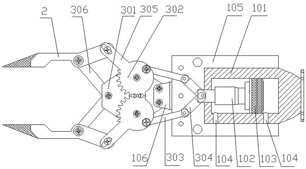
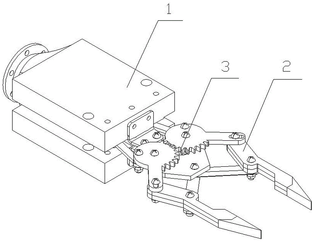
[0018] Such as figure 1 and figure 2 As shown, a grabbing manipulator of the present invention includes a driving mechanism 1, two claws 2 and a device for connecting the driving mechanism 1 and the two claws 2 and controlling the two claws according to the output of the driving mechanism 1 2 Complete torque transmission mechanism 3 for clamping or loosening. The driving mechanism 1 is a linear cylinder, the driving medium is compressed air, and the torque transmission mechanism 3 is mechanical, which not only has low manufacturing cost, but also has a stable structure and a long service life.

[0019] The driving mechanism 1 includes a cylinder body 101 with a shaft hole at one end and a piston rod 102 with a shaft diameter corresponding to the shaft hole. The piston rod 102 is slidably arranged in the shaft hole through a dynamic seal, one end of which is arranged in the inner chamber of the cylinder body 101 , and the other end extends out of the inner chamber of the cyl...


PUM


Abstract

The invention provides a gripping manipulator. The gripping manipulator includes a drive mechanism, claw forceps and a torque transmission mechanism. The drive mechanism is a linear air cylinder, the torque transmission mechanism includes a connection plate fixed on a cylinder body, the connection plate is provided with two gears meshed with each other, the two gears are hinged to first connection rods and fixedly provided with third connection rods respectively, the other end of each first connection rod is hinged to a second connection rod, the other end of each second connection rod is hinged to a piston rod, the other ends of the third connection rods are hinged to the tail portions of the two claw forceps respectively, the end, away from the cylinder body, of the connection plate is hinged to two fourth connection rods, and the ends, away from the connection plate, of the two fourth connection rods are hinged to the middle portions of the two claw forceps respectively. The gripping manipulator is low in cost and can effectively solve the problems that the operation speed of the manipulator is unstable and speed loss occurs in the prior art.

Description

technical field [0001] The invention relates to the field of material grabbing equipment, in particular to a grabbing manipulator. Background technique [0002] At present, manipulators appear in many comprehensive technical fields, which can replace manpower to carry materials or perform some dangerous actions such as detonation. In the production of modern machinery industry, a large number of automated machinery replace workers to complete work in harsh environments. At the same time, its high-speed work efficiency is unmatched by workers. Similarly, automated machinery does not need to rest and can work 24 hours a day. , but most of the industrial manipulators in the current industrial assembly line are driven by electricity, and the operation speed adjustment is generally realized by a series of complex and precise mechanisms such as frequency conversion motors or gearboxes. The cost is high and the speed adjustment is unstable, accompanied by Problems such as speed lo...

Claims


Application Information

Patent Timeline
Patent Type & Authority Applications(China)
IPC IPC(8): B25J15/02
CPCB25J15/0213
Inventor 李彬王红巍然
Owner LUOYANG INST OF SCI & TECH
Why Eureka
Try Eureka