
An experimental device for measuring the critical point of thermal deformation of a CNC machine tool bed and its determination method

A determination method and thermal deformation technology, applied in the field of CNC machine tools, can solve the problems of reducing the machining accuracy of machine tools, uneven temperature changes, and great influence of precision machining.

Active Publication Date: 2020-08-28
ANHUI UNIV OF SCI & TECH
View PDF4 Cites 0 Cited by
  • Summary
  • Abstract
  • Description
  • Claims
  • Application Information

AI Technical Summary

Problems solved by technology

The error caused by the thermal deformation of the machine tool is called thermal deformation error. Due to the influence of heat sources such as friction heat, cutting heat, external environment temperature changes, and heat radiation, as well as the uneven distribution of heat sources and the complexity of the machine tool structure, the temperature of each part of the machine tool Uneven changes will occur, which have a great impact on precision machining, and the proportion of workpiece size error and shape error caused by it can account for 40% to 70%, thereby reducing the machining accuracy of the machine tool

Method used


Image

  • An experimental device for measuring the critical point of thermal deformation of a CNC machine tool bed and its determination method
  • An experimental device for measuring the critical point of thermal deformation of a CNC machine tool bed and its determination method
  • An experimental device for measuring the critical point of thermal deformation of a CNC machine tool bed and its determination method

Examples


Embodiment Construction

[0021] In order to make the technical means, goals and effects realized by the present invention easy to understand, the present invention will be further described in detail below in conjunction with specific examples and illustrations. It should be understood that these descriptions are exemplary only, and are not intended to limit the scope of the present invention.

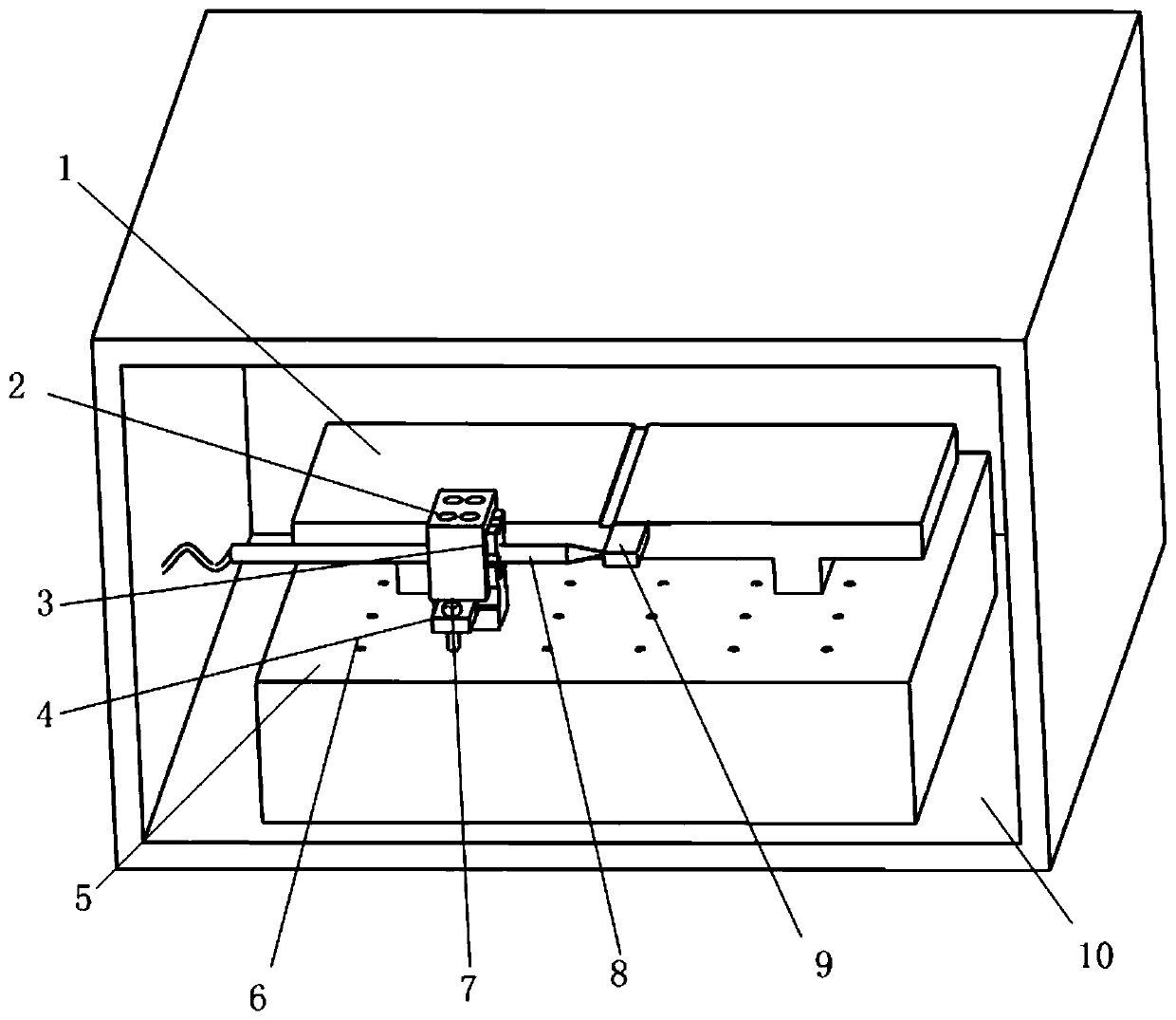
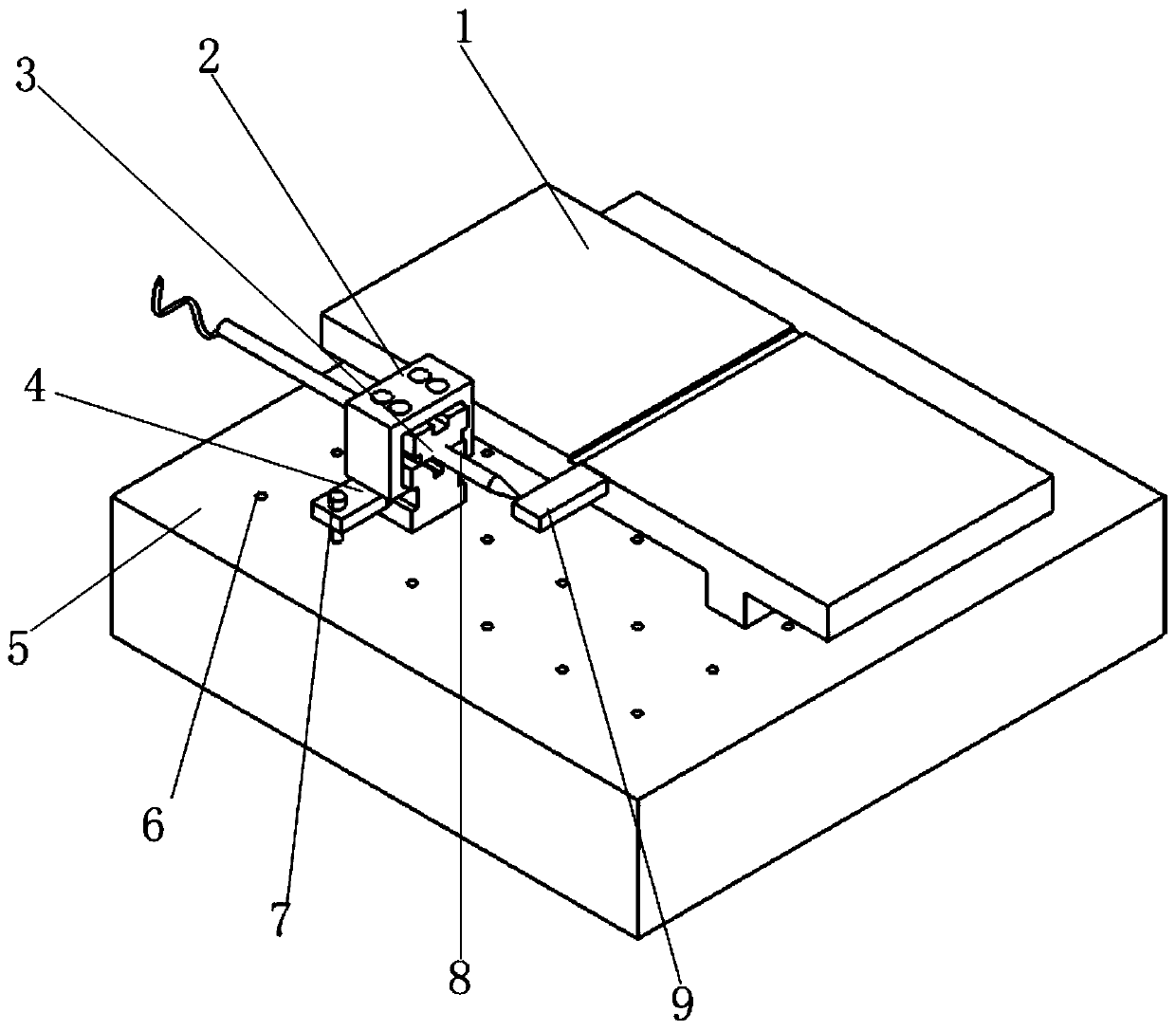
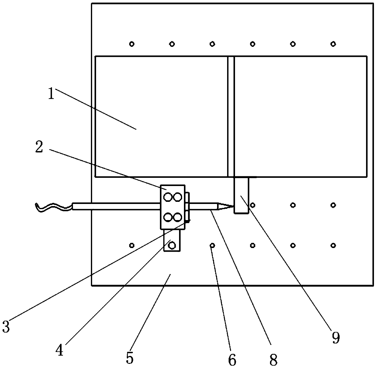
[0022] Such as figure 1 As shown, an experimental device for measuring the thermal deformation critical point of a CNC machine bed, including a machine bed miniature model 1, a clamping part 2, a V-shaped block 3, a pressure plate 4, a marble platform 5, a threaded hole 6, a screw 7, an inductor Micrometer 8, Invar block 9, temperature control box 10. Such as figure 1 As shown in , the V-shaped block 3 is firmly fixed on the marble platform 5 by the pressure plate 4 and the screw 7; the inductance micrometer 8 is fixed by the combined fixture composed of the clamping part 2 and the V-shaped block 3 .

[002...


PUM


Abstract

The invention discloses a measurement experiment device and determining method for a thermal deformation critical point of a numerical control machine tool, and the device comprises a temperature control box, a machine tool body microform model, a marble platform, a V-shaped block, a clamping part, a pressure plate, a threaded hole, a screw, an inductive amesdial, and an invar block. The temperature control box is used for simulating the temperature changes of the machine tool body in an actual machining process in four seasons of a year, provides temperature change conditions for an experiment process, and facilitates the stable measurement. The machine tool body model is a small-size model which is machined according the similarity principle through the size of an actual numerical control machine tool. The marble platform is good in stability and is small in coefficient of thermal expansion, so the marble platform can serve as a placement platform of a clamping tool and the machine tool body model. The V-shaped block, the clamping part, the pressure plate, the threaded hole, the screw and the inductive amesdial are installed to be a combined clamping tool to be fixed on the marble platform. The invar block is small in coefficient of thermal expansion and is hardly affected by the thermal deformation, so the invar blokc can serve as a mark block for representing the thermal deformation quantity of a point on a grid installation line of the machine tool body.

Description

technical field [0001] The invention relates to the field of numerical control machine tools, in particular to an experimental device for measuring a critical point of thermal deformation of a bed of a numerical control machine tool and a determination method. Background technique [0002] During the machining process of the machine tool, the deformation of the process system is caused by the friction heat, cutting heat and external heat source caused by the moving parts of the machine tool. This deformation is called thermal deformation. The error caused by the thermal deformation of the machine tool is called thermal deformation error. Due to the influence of heat sources such as friction heat, cutting heat, external environment temperature changes, and heat radiation, as well as the uneven distribution of heat sources and the complexity of the machine tool structure, the temperature of each part of the machine tool Uneven changes will occur, which have a great impact on p...

Claims


Application Information

Patent Timeline
Patent Type & Authority Patents(China)
IPC IPC(8): G01M99/00G01B7/16
CPCG01B7/16G01M99/002
Inventor 杨洪涛李莉张铈岱庞勇军陈邦晟喻曹丰
Owner ANHUI UNIV OF SCI & TECH
Learn More