
Active pen, step-up circuit and control method

A technology of a boost circuit and a control method, which is applied in the direction of control/regulation system, electrical components, and adjustment of electrical variables, etc., which can solve problems such as non-adjustability, inability to improve circuit signal-to-noise ratio, and inability to reduce system power consumption, so as to reduce system power consumption. Power consumption, the effect of improving the signal-to-noise ratio

Active Publication Date: 2017-12-05
SHENZHEN GOODIX TECH CO LTD
View PDF8 Cites 11 Cited by
  • Summary
  • Abstract
  • Description
  • Claims
  • Application Information

AI Technical Summary

Problems solved by technology

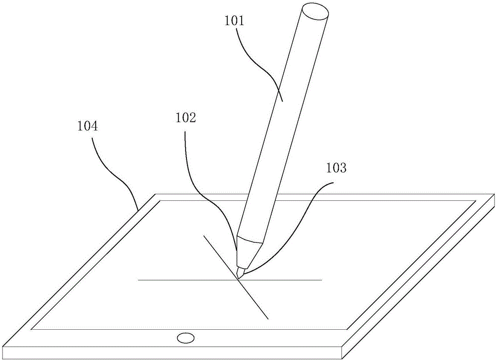
[0004] In the process of implementing this application, the inventor found that there are at least the following problems in the prior art: the current solution for pen tip 103 to realize high-voltage coding is mainly LC resonance coding. In the LC resonance circuit, the inductor and capacitor form a series resonance circuit. The power supply in the pen 101 provides energy input for the LC resonant circuit, and the LC resonant circuit outputs a high-voltage coding signal to the pen tip; however, in the LC resonant circuit, after the inductance and capacitance are selected, the circuit output high-voltage frequency is fixed and cannot be adjusted, so that The signal-to-noise ratio of the circuit is fixed and cannot be improved; at the same time, the output high voltage range of the circuit is also fixed and cannot be adjusted, which cannot reduce system power consumption

Method used


Image

  • Active pen, step-up circuit and control method
  • Active pen, step-up circuit and control method
  • Active pen, step-up circuit and control method

Examples


Embodiment Construction

[0033] In order to make the purpose, technical solution and advantages of the present application clearer, some embodiments of the present application will be further described in detail below in conjunction with the accompanying drawings and embodiments. It should be understood that the specific embodiments described here are only used to explain the present application, and are not intended to limit the present application.

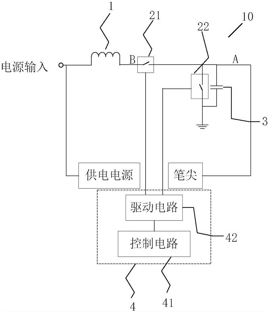
[0034] The first embodiment of the present application relates to a boost circuit applied to an active pen, capable of outputting a high-voltage coding signal to the pen tip of the active pen when the power supply of the active pen provides energy input. Please refer to figure 2 , the boost circuit 10 includes an inductor 1 , a switch module, a capacitor 3 and a control module 4 .

[0035]The switch module includes at least a first switch 21 and a second switch 22, the capacitor 3 is connected in parallel with the second switch 22; the first end of th...


PUM


Abstract

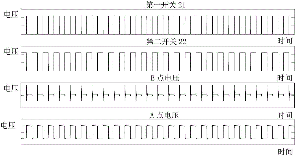
The invention proposes an active pen, a step-up circuit and a control method thereof. A boost circuit (10) comprises an inductor (1), a switch module, a capacitor (3) and a control module (4); the switch module at least comprises a first switch (21) and a second switch (22), a first end of the first switch is connected to one end of the inductor and a second end of the second switch is connected in parallel with the second switch; is connected to a first end of the second switch (22), and a second end of the second switch (22) is grounded; the other end of the inductor (1) is used for connecting to a power supply; the control module 4) is connected to the control terminal of the switch module; the control module (4) is used to control the state of each switch in the switch module so that the first end of the second switch (22) outputs a preset frequency And the amplitude of the voltage signal. The control method can improve the signal-to-noise ratio of the communication signal by using the frequency hopping communication technology, and meanwhile can reduce the system power consumption by adjusting the code voltage amplitude according to the application scenario.

Description

technical field [0001] The present application relates to the technical field of booster circuits, in particular to an active pen, a booster circuit and a control method thereof. Background technique [0002] At present, more and more terminal devices have touch screens, and the active pen 101 can be used to write or input instructions to terminal devices 104 with touch screens, such as computer screens, mobile terminal devices, drawing tablets, etc., to realize human-computer interaction, such as figure 1 shown. [0003] The nib 103 at the end of the nib 102 of the active pen 101 outputs a coding signal to realize the communication between the active pen 101 and the terminal device 104 with a touch screen. The signal-to-noise ratio of communication signals between the terminal devices 104 of the touch screen. [0004] In the process of implementing this application, the inventor found that there are at least the following problems in the prior art: the current solution fo...

Claims


Application Information

Patent Timeline
IPC IPC(8): H02M3/156H02M3/158
CPCH02M3/156H02M3/158G06F3/03545G06F3/0383
Inventor 李梦平杜灿鸿
Owner SHENZHEN GOODIX TECH CO LTD
Learn More