
Prefabricated bearing platform form and mounting method thereof

A prefabricated platform and installation method technology, applied in the field of building formwork, can solve problems such as affecting the foundation construction process, large on-site masonry workload, difficult quality control, etc., to achieve the effect of improving assembly efficiency, shortening construction period and saving labor.

Pending Publication Date: 2017-12-08
佛山市万科置业有限公司
View PDF3 Cites 4 Cited by
  • Summary
  • Abstract
  • Description
  • Claims
  • Application Information

AI Technical Summary

Problems solved by technology

[0004] The traditional brick formwork wall needs to wait until the masonry shear strength meets the requirements before backfilling and compacting the outer area, which seriously affects the foundation construction process; moreover, when the geological conditions are poor, the brick formwork is prone to collapse phenomenon; in addition, the traditional brick tire formwork masonry method has many disadvantages such as heavy on-site masonry workload, high material consumption, and difficult quality control.

Method used


Image

  • Prefabricated bearing platform form and mounting method thereof
  • Prefabricated bearing platform form and mounting method thereof
  • Prefabricated bearing platform form and mounting method thereof

Examples


Embodiment Construction

[0060] Embodiments of the present invention will be described in detail below.

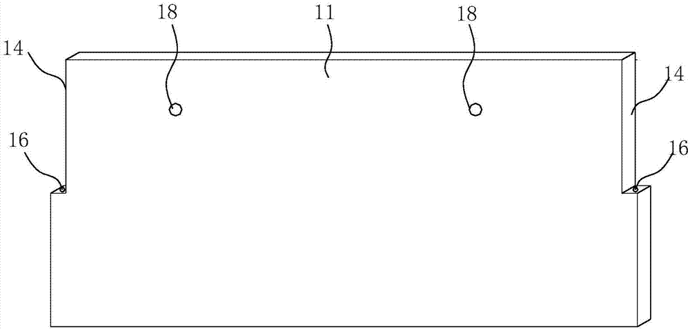
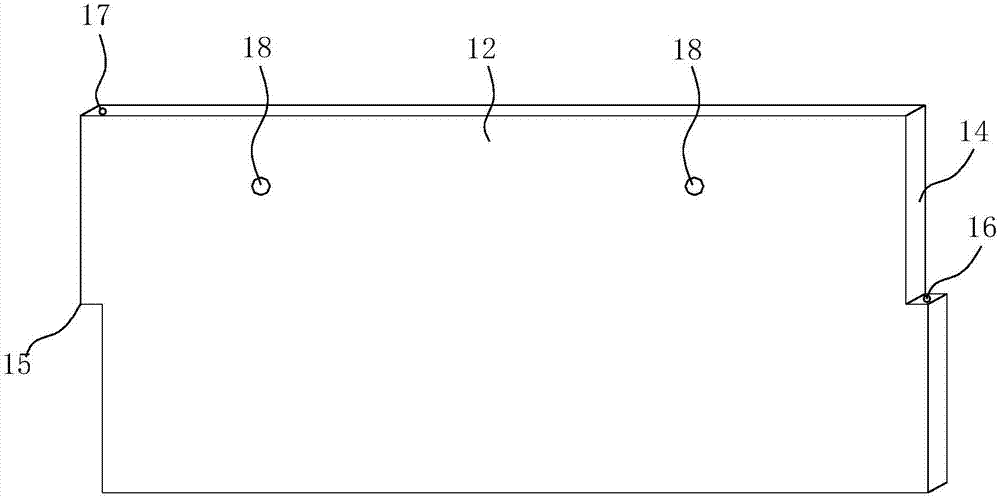
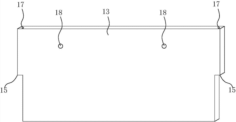
[0061] Such as Figure 1 to Figure 6 As shown, the prefabricated cap formwork includes a plurality of plate bodies which are matched and connected head to tail in sequence. The two ends of the plate body are the first end and the second end. There is an upper tenon notch 14 or a lower tenon notch 15, and the upper tenon notch 14 matches the lower tenon notch 15;

[0062] When the first end of the plate is mated with the second end of the adjacent plate, the upper concave tenon notch 14 on the end face of the first end of the plate and the second end end of the adjacent plate Lower concave tenon notch 15 is matched and assembled.

[0063] Wherein, the upper tenon notch 14 includes a half protrusion and a half through notch, the half protrusion of the upper tenon notch 14 is below, the half through notch is above, and the lower tenon notch 15 includes a half protruding part, half-side through not...


PUM

PropertyMeasurementUnit
Diameteraaaaaaaaaa

Abstract

The invention discloses a prefabricated bearing platform form and a mounting method thereof. The prefabricated bearing platform form comprises a plurality of plate bodies which are in sequential matched end-to-end connection, wherein upper concave tongue-and-groove openings or lower concave tongue-and-groove openings are formed in two sides of the plate bodies, and the upper concave tongue-and-groove openings and the lower concave tongue-and-groove openings are matched with each other; and when the plate bodies are in matched connection with the adjacent plate bodies, the upper concave tongue-and-groove openings in the plate bodies are spliced with the lower concave tongue-and-groove openings of the adjacent plate bodies. The mounting method of the prefabricated bearing platform form comprises the following steps: pouring of a bedding layer of a bearing platform; lofting of the bearing platform; hoisting and splicing of the plate bodies; axis location; elevation review, back-filling treatment; and pouring of the bearing platform after back-filling and compacting. The prefabricated bearing platform form replaces a brick membrane, shortens the foundation construction period, can effectively save the labor force and raw materials particularly for foundations with tight schedules and poor foundation soil qualities, decreases cost and increases benefits, and has good economic benefits and social benefits.

Description

technical field [0001] The invention relates to the field of building formwork, in particular to a prefabricated platform formwork and an installation method thereof. Background technique [0002] In the foundation construction stage of existing buildings, brick tire formwork is widely used in the underground structure to serve as the outer formwork; especially when the foundation cap, foundation beam and bottom plate are integrated, and the supported formwork cannot be removed, brick tire formwork must be used ; In addition, when the slope of the foundation pit is not enough and there is not enough formwork operating surface at the bottom of the foundation pit, brick tire formwork is also required. [0003] The traditional brick formwork construction method is to use blocks to build masonry after the earthwork is excavated to the elevation and the cushion construction is completed, and the inside of the brick formwork is plastered with cement mortar; after the brick wall re...

Claims


Application Information

Patent Timeline
IPC IPC(8): B28B7/26E02D27/14
CPCE02D27/14B28B7/263
Inventor 李康毛君
Owner 佛山市万科置业有限公司
Learn More