Cutting method of workpiece

A technology for workpiece cutting and processing, which is applied to work accessories, manufacturing tools, stone processing equipment, etc., can solve problems such as poor wafer quality, and achieve the effects of avoiding the risk of disconnection, improving processing quality, and improving quality

Active Publication Date: 2019-05-10
SUMCO CORP
View PDF5 Cites 0 Cited by
  • Summary
  • Abstract
  • Description
  • Claims
  • Application Information

AI Technical Summary

Problems solved by technology

However, there is a problem that the quality of the wafer near both ends of the workpiece is poor

Method used


Image

  • Cutting method of workpiece
  • Cutting method of workpiece
  • Cutting method of workpiece

Examples


Embodiment Construction

[0021] Hereinafter, preferred embodiments of the present invention will be described in detail with reference to the drawings.

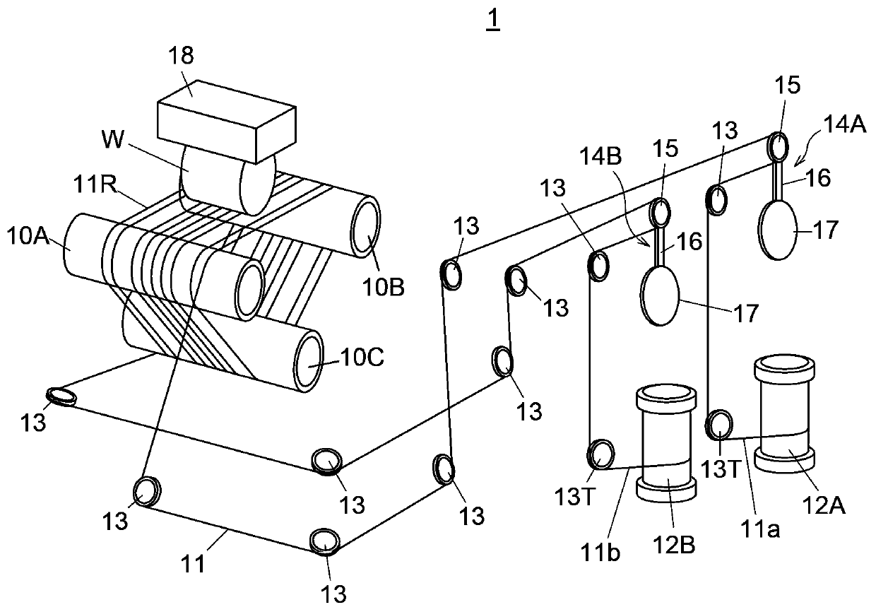
[0022] figure 1 It is a perspective view which schematically shows the whole structure of the wire saw 1 which concerns on embodiment of this invention.

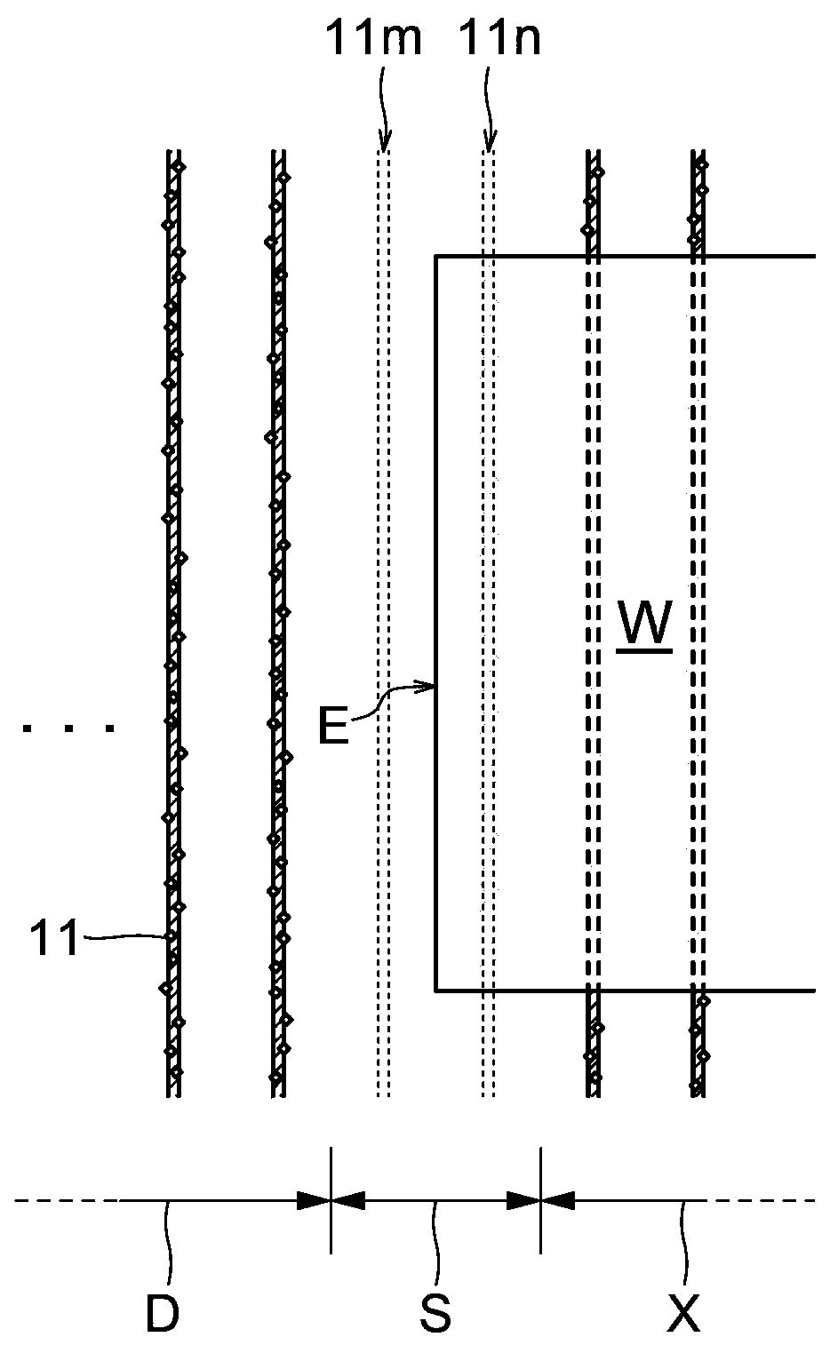
[0023] Such as figure 1 As shown, the wire saw 1 includes three main rollers 10A, 10B, and 10C arranged in parallel to each other, and a wire row 11R formed by winding one wire 11 multiple times between the three main rollers 10A, 10B, and 10C. First and second reels 12A, 12B for winding one end 11a and the other end 11b of the wire 11, a plurality of guide rollers 13 including a traverse roller 13T, and a pair of tension regulators for adjusting the tension of the wire 11 Mechanisms 14A, 14B.

[0024] The main rolls 10A, 10B, and 10C are grooved rolls, and a large number of annular grooves are formed at regular intervals on the outer peripheral surface. As the main roll, for example, a structu...


PUM


Abstract

The invention realizes prevention of wire materia cutting-off risk and quality improvement of wafers at two ends of a workpiece. The workpiece cutting-off method is characterized in that wire material row (11R) is formed through hanging a wire (11) between a plurality of parallel main rollers (10A,10B) by multiple times; the workpiece is machined to a wafer-shaped member through abutting against a wire row (11R) in an advancing state by the workpiece (W); and a wire saw is utilized. The wire row (11R) comprises the components of a real wire arranging area (X), wherein in a workpiece cutting-off area which is closer to inside than two ends of the workpiece, the wires (11) are arranged in a certain distance and contact with the workpiece in performing cutting-off processing on the workpiece; a wire jumping area (S) which is next to two ends of the workpiece, and the wires (11) are not arranged in a certain distance; and a first pseudo wire arranging area (D) which is outside the wire jumping area (S), wherein after more than two wires (11) are arranged in the certain distance, the wires are leaded to outside the hanging ring of the plurality of main rollers, and the wires do not contact with any workpiece in cutting-off the workpiece.

Description

technical field [0001] The present invention relates to a method of cutting a workpiece, and to a method of arranging wire rods wound multiple times between a plurality of main rolls. Background technique [0002] Materials such as silicon, sapphire, and SiC used in semiconductor equipment are processed into a cylindrical shape by various methods, and then sliced ​​into a wafer shape, followed by grinding, cleaning, etc., to become finished wafer. In the slicing process of the billet, a wire saw is mainly used, and the wire rod wound multiple times between the main rollers in parallel is advanced, and the billet as the workpiece fixed to the workpiece holder via the adhesive layer is pushed Slicing the briquette to the target thickness against the advancing wire. [0003] In the cutting process with a wire saw, the end material of the workpiece is separated from the adhesive layer during the cutting of the workpiece or when the cutting is completed, and the end material is...

Claims


Application Information

Patent Timeline
Patent Type & Authority Patents(China)
IPC IPC(8): B28D5/04B28D7/00
CPCB28D5/042B28D7/00
Inventor 卫藤义博又川敏
Owner SUMCO CORP
Why Eureka
Try Eureka