Mounting structure of wire wheels of diamond wire cutting machine

A technology of diamond wire and installation structure, which is applied to fine working devices, stone processing equipment, manufacturing tools, etc., can solve problems such as diamond wire breakage, achieve the effect of reducing frictional resistance and avoiding the risk of wire breakage

Active Publication Date: 2019-05-21
义乌市鼎莎针织有限公司
View PDF10 Cites 0 Cited by
  • Summary
  • Abstract
  • Description
  • Claims
  • Application Information

AI Technical Summary

Problems solved by technology

[0005] Aiming at the deficiencies in the use process of the existing diamond wire cutting machine guide wheel installation mechanism proposed in the background technology, the present invention provides a diamond wire cutting machine guide wheel installation structure, which has the ability to prevent the diamond wire from being broken when it encounters a hard point. Advantages, it solves the problem that the diamond wire is prone to breakage when it encounters a hard point due to the fixed installation mechanism of the guide wheel proposed in the above background technology

Method used


Image

  • Mounting structure of wire wheels of diamond wire cutting machine
  • Mounting structure of wire wheels of diamond wire cutting machine
  • Mounting structure of wire wheels of diamond wire cutting machine

Examples


Embodiment Construction

[0021] The following will clearly and completely describe the technical solutions in the embodiments of the present invention with reference to the accompanying drawings in the embodiments of the present invention. Obviously, the described embodiments are only some, not all, embodiments of the present invention. Based on the embodiments of the present invention, all other embodiments obtained by persons of ordinary skill in the art without making creative efforts belong to the protection scope of the present invention.

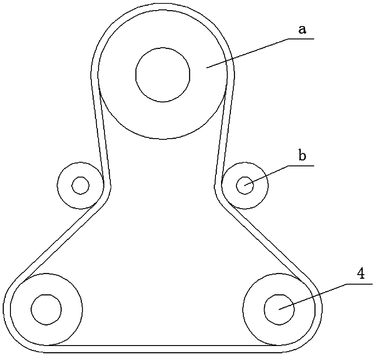
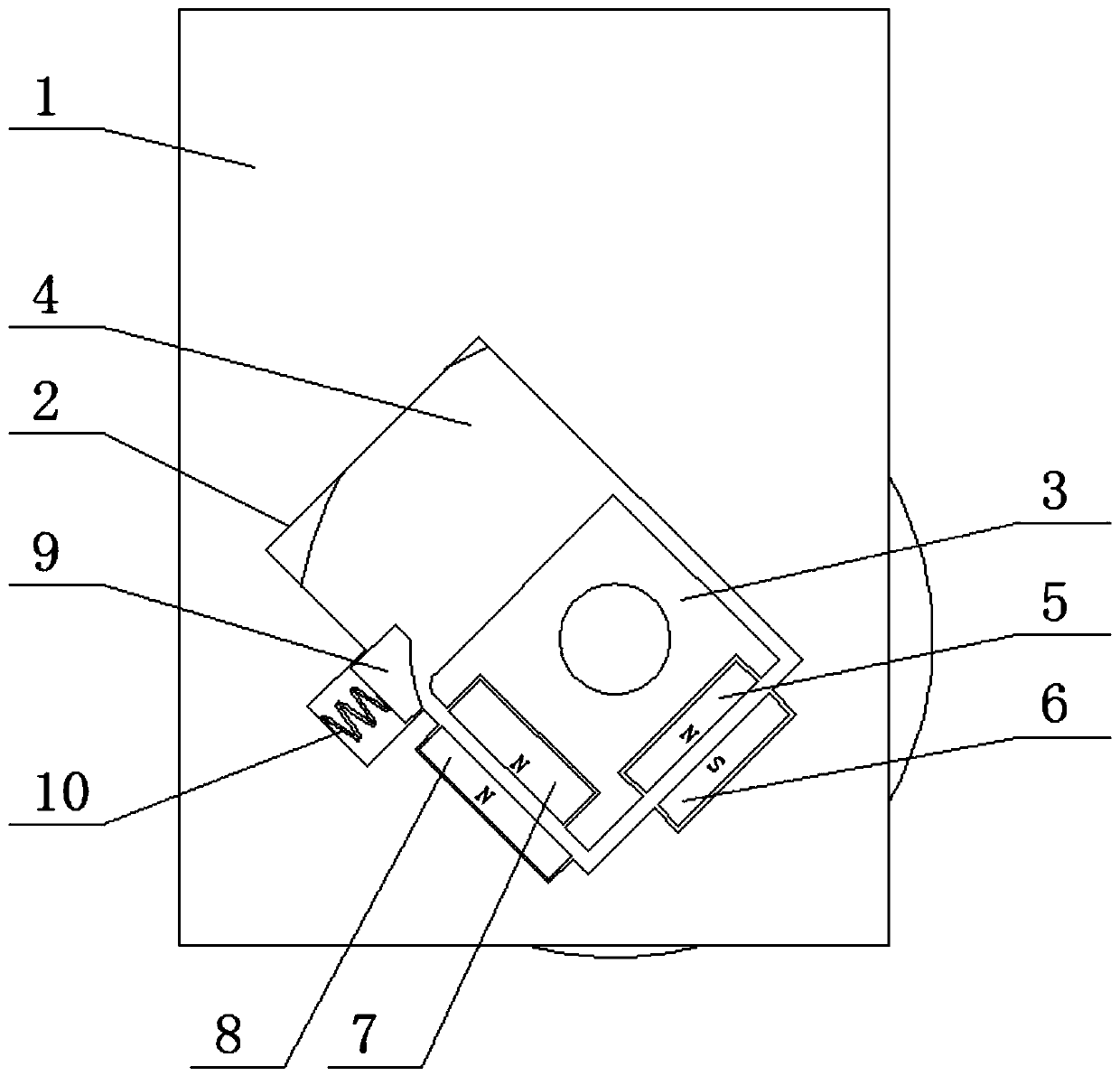
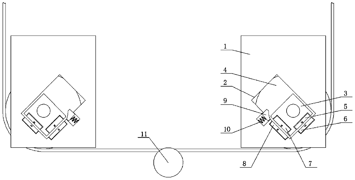
[0022] see Figure 1-4 , a mounting structure of the guide wheel of a diamond wire cutting machine, which is different from the traditional fixed positioning installation method of the guide wheel. The traditional fixed installation method fixes the central rotating shaft of the guide wheel 4 on the mounting plate 1, while the present application uses such as figure 2 The installation structure shown includes the guide groove 2 opened on the front of the inst...


PUM

PropertyMeasurementUnit
Angleaaaaaaaaaa

Abstract

The invention relates to the technical field of photovoltaic equipment, and discloses a mounting structure of wire wheels of a diamond wire cutting machine. The mounting structure comprises a mountingplate; a guiding slot is formed in the obverse side of the mounting plate; the guiding slot is of a rectangular aslant-arranged hole; a guiding sliding block is connected with the inner part of the guiding slot in a clamping manner and can be slid in an inner cavity of the guiding slot; and the back of the guiding sliding block is fixedly connected with a central rotating shaft of the wire wheel.According to the mounting structure of the wire wheels of the diamond linear cutting machine disclosed by the invention, the wire wheels are fixedly mounted on the mounting plate through magnetic force, the wire wheels can slide and climb up in the guiding slot along with the guiding sliding block; the guiding slot is aslant arranged, and the guiding sliding block can be pulled and climbed up because of the designed tension force when a diamond wire is tightened because a hard point of a crystal is cut by the diamond wire, so that a space between the two wire wheels is reduced to ensure thatthe diamond wire positioned between the two wire wheels reaches a loosening state, and meanwhile, the two wire wheels are climbed up, so that the diamond wire positioned between the two wire wheels isupwards away from the hard point of the crystal; and therefore, a comprehensive effect ensures that avoidance of the risk of wire breakage of the diamond wire.

Description

technical field [0001] The invention relates to the technical field of photovoltaic equipment, in particular to a mounting structure for a guide wheel of a diamond wire cutting machine. Background technique [0002] In order to solve the processing problem of large-size silicon wafers, the processing technology of diamond wire cutting or mortar cutting is adopted. Compared with mortar cutting, diamond wire cutting has the advantages of fast cutting speed and low single chip loss, which greatly reduces Silicon cost for wafer production. [0003] The diamond wire is made by uniformly fixing the diamond micropowder particles on the high-strength steel wire substrate with a certain distribution density by a certain method, and then winding the diamond wire on the diamond wire cutting machine, such as figure 1 In the shown winding method, wherein, the winding drum a is a winding roller, the tension wheel b is a tensioning diamond wire wheel, and the diamond wire is reciprocating...

Claims


Application Information

Patent Timeline
IPC IPC(8): B28D5/00B28D5/04
Inventor 不公告发明人
Owner 义乌市鼎莎针织有限公司
Why Eureka
Try Eureka