Device for reducing wire jumping rate in silicon rod cutting and cutting method

A cutting method and wire skipping rate technology, which is applied in the field of devices for reducing the wire jumping rate of silicon rod cutting, can solve the problems of wire jumping, reduce the wire jumping rate of silicon rod cutting, diamond wires are easily squeezed out of the groove by foreign objects, and achieve Make up for the hidden danger of disconnection and avoid the effect of jumping wires

Pending Publication Date: 2022-05-06
GUANGDONG GOKIN SOLAR ENERGY TECH CO LTD
View PDF0 Cites 0 Cited by
  • Summary
  • Abstract
  • Description
  • Claims
  • Application Information

AI Technical Summary

Problems solved by technology

[0004] In view of the above problems, the purpose of the present invention is to propose a device for reducing the jumping rate of silicon rod cutting, so as to solve the problem that diamond wires are easily squeezed out of the groove by foreign matter during high-speed cutting in the traditional silicon rod cutting process and cause wire jumping.

Method used


Image

  • Device for reducing wire jumping rate in silicon rod cutting and cutting method
  • Device for reducing wire jumping rate in silicon rod cutting and cutting method
  • Device for reducing wire jumping rate in silicon rod cutting and cutting method

Examples


Embodiment 1

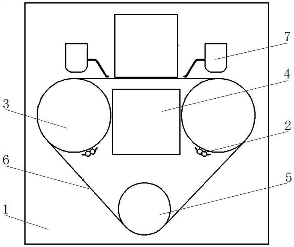
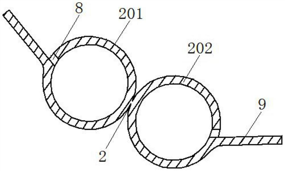
[0028] see figure 1 , figure 2 , this embodiment provides a device for reducing wire skipping rate in silicon rod cutting, which includes a slicer body 1 and an air duct assembly 2, the slicer body 1 is symmetrically provided with main rollers 3, and between the two main rollers 3 is a Fragment groove 4, a small roller 5 is arranged below the fragment groove 4, diamond wire 6 is arranged on the main roller 3 and the small roller 5, and the diamond wire 6 is arranged in the wire groove on the main roller 3 and the small roller 5, and the upper part of the main roller 3 A mortar pipe 7 is provided, and the air duct assembly 2 is arranged below the main roller 3. One end of the air duct assembly 2 is fixed on the inner wall of the slicer body 1, and the other end of the air duct assembly 2 is connected to the bronchial interface on the inner wall of the slicer body 1. Both sides of the air duct assembly 2 are provided with air outlets 8, and both sides of the air duct assembly ...

Embodiment 2

[0039] see figure 1 , figure 2 , this embodiment provides a device for reducing wire skipping rate in silicon rod cutting, which includes a slicer body 1 and an air duct assembly 2, the slicer body 1 is symmetrically provided with main rollers 3, and between the two main rollers 3 is a Fragment groove 4, a small roller 5 is arranged below the fragment groove 4, diamond wire 6 is arranged on the main roller 3 and the small roller 5, and the diamond wire 6 is arranged in the wire groove on the main roller 3 and the small roller 5, and the upper part of the main roller 3 A mortar pipe 7 is provided, and the air duct assembly 2 is arranged below the main roller 3. One end of the air duct assembly 2 is fixed on the inner wall of the slicer body 1, and the other end of the air duct assembly 2 is connected to the bronchial interface on the inner wall of the slicer body 1. Both sides of the air duct assembly 2 are provided with air outlets 8, and both sides of the air duct assembly ...


PUM

PropertyMeasurementUnit
diameteraaaaaaaaaa

Abstract

The invention discloses a device for reducing the wire jumping rate of silicon rod cutting and a cutting method. The device comprises a slicing machine body and an air pipe assembly, main rollers are symmetrically arranged on the slicing machine body, a fragment groove is formed between the two main rollers, a small roller is arranged below the fragment groove, and diamond wires are distributed on the main rollers and the small roller; the air pipe assembly is arranged below the main roller, the air outlets are formed in the two sides of the air pipe assembly, when the branch air pipes supply air, the symmetrical air knife-like design is formed, air flow periodically cleans the wire groove of the main roller in the rotating direction of the main roller in the cutting process, silicon powder and other foreign matter are prevented from being accumulated in the wire groove, and the service life of the wire groove is prolonged. According to the diamond wire cutting method, the risks of wire jumping and even wire breaking caused by the fact that the diamond wire is extruded out of a wire groove by foreign matter during high-speed cutting are avoided, the hidden danger of wire breaking caused by groove body defects is effectively made up when the diamond wire becomes thinner and thinner, and in the cutting method, points where impurities are likely to accumulate and become the hidden danger are cleaned in a targeted mode; and the influence on the diamond wire in the cutting process is avoided.

Description

technical field [0001] The invention relates to the technical field of silicon rod cutting, in particular to a device and a cutting method for reducing the jump rate of silicon rod cutting. Background technique [0002] In the field of photovoltaic slicing, diamond wire cutting has eliminated the traditional mortar cutting with an absolute advantage. In order to ensure the stability of the steel wire in the groove, the processing of the main roller will also match with the diamond wire, resulting in a smaller groove distance. In order to ensure the strength of the groove, the groove depth is usually appropriately reduced. . [0003] During the cutting process of silicon rods, the concentration of silicon powder in the mortar liquid will become higher and higher. At the same time, the impurities that have not been cleaned up after the processing of the previous silicon rod will circulate with the cutting fluid when cutting the next silicon rod. The system re-enters the cutt...

Claims


Application Information

Patent Timeline
Patent Type & Authority Applications(China)
IPC IPC(8): B28D5/04B28D7/00B28D7/02B28D7/04B24B27/06
CPCB28D5/045B28D5/007B28D5/0058B28D5/0076B28D5/0082B24B27/0633
Inventor 徐志群孙彬付明全罗琨郭翔毕喜行
Owner GUANGDONG GOKIN SOLAR ENERGY TECH CO LTD
Why Eureka
Try Eureka