
Air conditioning system and control device and method of air conditioning system

A technology of an air conditioning system and a control device is applied in the field of an air conditioning system, a control method of an air conditioning system, a non-transitory computer-readable storage medium, and a control device of an air conditioning system, and can solve the hidden danger of compressor reliability and safety, and system refrigeration. It can improve the experience, improve reliability, and improve cooling performance.

Inactive Publication Date: 2017-12-08
WUHAN REFRIGERATION EQUIP OF MIDEA GROUP +1
View PDF8 Cites 8 Cited by
  • Summary
  • Abstract
  • Description
  • Claims
  • Application Information

AI Technical Summary

Problems solved by technology

However, the problem with related technologies is that high-energy-efficiency systems generally use small-displacement compressors, and the amount of refrigerant exceeds the maximum charge of the compressor, which poses a greater safety hazard to the compressor's liquid return, oil return, and reliability. , Moreover, when the compressor is running at low frequency, the flow rate of the system is small, and the refrigerant basically accumulates in the condenser, resulting in less refrigerant in the evaporator, resulting in fluctuations in the return air temperature of the compressor and higher temperatures , the cooling capacity of the system decreases, and the EER (Energy Efficiency Ratio, the cooling performance coefficient of the air conditioner) decreases significantly

Method used


Image

  • Air conditioning system and control device and method of air conditioning system
  • Air conditioning system and control device and method of air conditioning system
  • Air conditioning system and control device and method of air conditioning system

Examples


Embodiment Construction

[0029] Embodiments of the present invention are described in detail below, examples of which are shown in the drawings, wherein the same or similar reference numerals designate the same or similar elements or elements having the same or similar functions throughout. The embodiments described below by referring to the figures are exemplary and are intended to explain the present invention and should not be construed as limiting the present invention.

[0030] The control device of the air conditioning system, the air conditioning system and the control method of the air conditioning system according to the embodiments of the present invention will be described below with reference to the accompanying drawings.

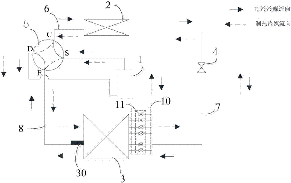
[0031] figure 1 is a schematic block diagram of a control device for an air conditioning system according to an embodiment of the present invention. Among them, according to figure 2 The embodiment of the air conditioning system may include a compressor 1, an outdoor...


PUM


Abstract

The invention discloses an air conditioning system and a control device and a method of the air conditioning system. A first port of an indoor heat exchanger is connected with a compressor through a third pipeline; a second port of the indoor heat exchanger is connected with an outdoor heat exchanger through a second pipeline; N branch circuits connected in parallel are connected with the second pipeline in a series or parallel manner; N valve modules are correspondingly arranged on the N branch circuits; each valve module is used for controlling opening or closing of the corresponding branch circuit; a first temperature detecting unit is used for detecting the refrigerant temperature of the indoor heat exchanger; a second temperature detecting unit is used for detecting the air suction temperature of the compressor; and a control unit is used for obtaining the temperature difference between the air suction temperature of the compressor and the refrigerant temperature of the indoor heat exchanger and controlling opening or closing of the N valve modules according to the temperature difference. The refrigerant flow of the air conditioning system can be controlled through controlling opening or closing of the valve modules, so that no overheating phenomenon of a refrigerant fed in the indoor heat exchanger is guaranteed, and the refrigeration performance of an air conditioner is improved.

Description

technical field [0001] The present invention relates to the technical field of air conditioning, in particular to a control device for an air conditioning system, an air conditioning system, a control method for an air conditioning system, and a non-transitory computer-readable storage medium. Background technique [0002] In the related art, the volume of the evaporator and the condenser of the frequency conversion high-energy-efficiency air-conditioning system are usually relatively large, and the system refrigerant charge is 30% higher than that of the ordinary air-conditioning system. However, the problem with related technologies is that high-energy-efficiency systems generally use small-displacement compressors, and the amount of refrigerant exceeds the maximum charge of the compressor, which poses a greater safety hazard to the compressor's liquid return, oil return, and reliability. , Moreover, when the compressor is running at low frequency, the flow rate of the sys...

Claims


Application Information

Patent Timeline
Patent Type & Authority Applications(China)
IPC IPC(8): F24F5/00F24F11/00F25B41/04F25B41/20
CPCF24F5/001F25B41/40F25B41/20
Inventor 徐志亮陈蒙
Owner WUHAN REFRIGERATION EQUIP OF MIDEA GROUP
Learn More