
Airflow direct connection wall hanging type fresh air ventilator

A wall-mounted, fresh air fan technology, applied in the field of fresh air fans, air flow straight through wall-mounted fresh air fans, can solve problems such as high noise, and achieve the effects of large air volume, noise reduction, and small noise

Pending Publication Date: 2017-12-08
陈罡
View PDF7 Cites 6 Cited by
  • Summary
  • Abstract
  • Description
  • Claims
  • Application Information

AI Technical Summary

Problems solved by technology

[0004] The purpose of the present invention is to provide a direct-flow wall-mounted fresh air fan in order to overcome the above-mentioned technical problem of high noise of the existing wall-mounted fresh air fan. In the indoor room, the airflow flow is straight through without redundant process. It mainly adopts multiple noise reduction and sound reduction technical measures such as double fans, hollow casing, and the main fan is placed behind the filter layer to achieve the effect of low noise and large air volume. The overall structure Reasonable, thin and light, easy to install

Method used


Image

  • Airflow direct connection wall hanging type fresh air ventilator
  • Airflow direct connection wall hanging type fresh air ventilator
  • Airflow direct connection wall hanging type fresh air ventilator

Examples


Embodiment 1

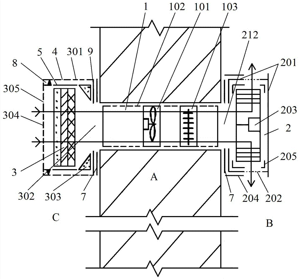
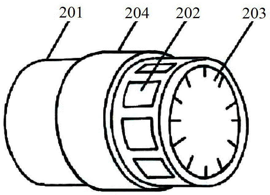
[0046] Such as figure 1 As shown, a wall-mounted fresh air blower with direct air flow includes: an external filter layer assembly, a booster fan assembly 1, and a main fan assembly 2 connected in sequence along the air supply direction, and the external filter layer assembly passes through the external casing main body 301 corresponding to The casing back plate 9 is set on the outer wall of the outer wall A of the room, the booster fan assembly 1 is buried in the wall hole of the outer wall A of the room, the main fan assembly 2 is installed on the inner wall of the outer wall A of the room, and enters the main fan The airflow path in front of the air inlet of component 2 is straight through, and the airflow behind the main fan outlet of main fan component 2 goes directly to room B in the room. The rotation planes are all parallel to the wall surface of the outer wall A, because the air flow is straight through, so that the frictional resistance of the air flow to the air duc...

Embodiment 2

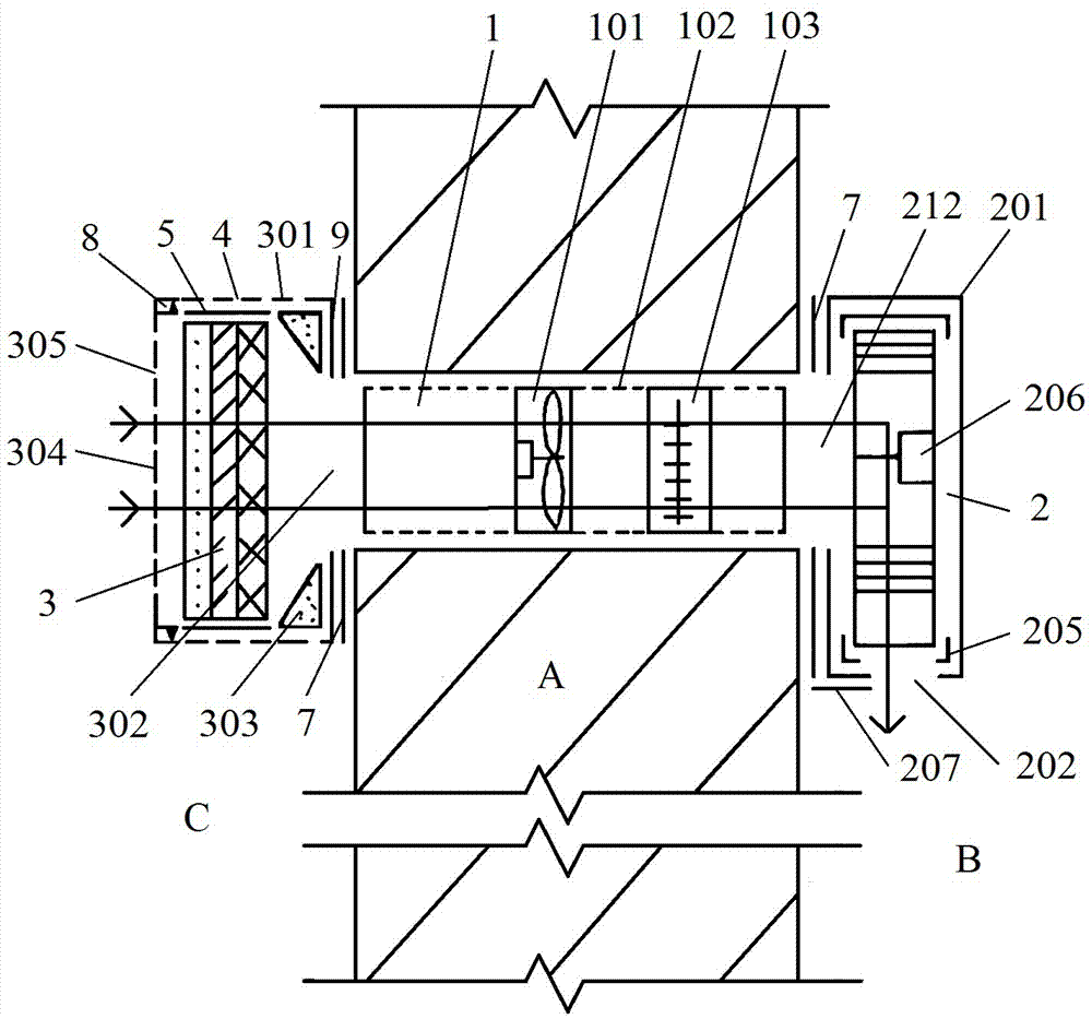
[0065] Such as image 3 As shown, a wall-mounted fresh air blower with direct airflow includes an external filter layer assembly, a booster blower assembly 1 and a main blower assembly 2. The difference between this embodiment and the first embodiment is that the main blower adopts a turbo fan 206 (with a volute) , the rotation plane of the impeller of the turbo fan 206 is parallel to the outer wall A of the room, the fresh air outlet 202 is set on the shell wall of the built-in casing main body 201, and is aligned with the air outlet of the turbo fan 206, and enters the airflow path before the air inlet of the main fan For direct connection, the airflow behind the air outlet of the main fan is directly connected to room B in the room. The fresh air outlet 202 can be square or circular. The valve slide plate 207 is closely attached to the outer wall of the built-in casing main body 201. The valve slide plate 207 is slidingly connected with the built-in casing main body 201. Th...

Embodiment 3

[0068] Such as Figure 4As shown, a wall-mounted fresh air blower with direct airflow includes an external filter layer assembly, a booster fan assembly 1 and a main fan assembly 2. The impeller rotation plane of 208 is parallel to the outer wall A of the room, and the fresh air outlet 202 is opened on the cross-section of the built-in casing main body 201, that is, the fresh air outlet 202 is the cross-section of the casing behind the outlet end of the axial flow fan 208, and the outlet valve Adjustable tuyere structure is adopted, including outlet support frame 209, adjustment rod 210 and tuyere baffle plate 211. The outlet support frame 209 is erected at the fresh air outlet 202. One end of the adjustment rod 210 is connected to the center of the outlet support frame 209, and the other end is connected to At the center of the tuyere baffle 211, the outlet valve is opened or closed by adjusting the distance between the tuyere baffle 211 and the fresh air outlet 202 to preven...


PUM


Abstract

The invention relates to a fresh air ventilator, in particular to an airflow direct connection wall hanging type fresh air ventilator, and belongs to the field of indoor ventilation and aeration equipment. The airflow direct connection wall hanging type fresh air ventilator comprises a power-assisted fan component, a main fan assembly and an external filtering layer, and the power-assisted fan component is buried in a wall hole of a room outer wall; the main fan assembly comprises an internal machine shell body installed at the inner side face of the room outer wall, a main fan and a fresh air outlet with an outlet valve, the main fan and the fresh air outlet are arranged in the internal machine shell body in the air supplying direction in sequence, a fresh air inlet connected with the air outlet end of the power-assisted fan component is formed in the back face of the internal machine shell body, and the impeller rotary plane of the main fan is parallel to the room outer wall. Compared with the prior art, the airflow path in front of a main fan inlet is directly connected, the airflow in front of a main fan outlet is directly connected to an indoor room, the airflow path is directly connected and free of a redundancy process, many technological measures for eliminating and reducing noise by arranging two fans, the hollow machine shell, the main fan on at the rear portion of the filtering layer and the like are mainly adopted, and the effects of small noise and a large air volume are achieved.

Description

technical field [0001] The invention relates to a fresh fan, in particular to a wall-mounted fresh fan with direct air flow, which belongs to the field of indoor ventilation equipment. Background technique [0002] With the improvement of people's pursuit of quality of life, more and more people hope to increase the inflow of outside air into the living room, but a larger ventilation volume often requires a higher-power fan, and the noise of a high-power fan will How to design fresh air fans with low noise and large air volume is a research direction. [0003] The main function of the fresh air fan is to draw outdoor natural air into the room to meet people's needs for oxygen indoors. When the quality of the outdoor air is poor, such as when there is PM2.5, or when the outdoor noise is loud , People often close the windows, so that the indoor oxygen content is low, and fresh air fans are needed. Fresh air fans generally have a filtering function. At present, more and more p...

Claims


Application Information

Patent Timeline
Patent Type & Authority Applications(China)
IPC IPC(8): F24F7/013F24F13/24F24F13/28
CPCF24F7/013F24F13/24F24F13/28F24F2013/247
Inventor 陈罡陈世明
Owner 陈罡
Learn More