
A Calculation Method for Harmonic Transfer Matrix of Power Induction Control Filter System

A technology of transfer matrix and calculation method, applied in harmonic reduction devices and AC networks to reduce harmonics/ripples, etc., and can solve problems such as less three-phase circuit analysis

Active Publication Date: 2020-10-27
HUNAN UNIV
View PDF3 Cites 0 Cited by
  • Summary
  • Abstract
  • Description
  • Claims
  • Application Information

AI Technical Summary

Problems solved by technology

At present, the quantitative analysis of induction control filter system is limited to the use of single-phase equivalent circuit, and seldom analyzed in three-phase circuit

Method used


Image

  • A Calculation Method for Harmonic Transfer Matrix of Power Induction Control Filter System
  • A Calculation Method for Harmonic Transfer Matrix of Power Induction Control Filter System
  • A Calculation Method for Harmonic Transfer Matrix of Power Induction Control Filter System

Examples


Embodiment Construction

[0016] The following will clearly and completely describe the technical solutions in the embodiments of the present invention with reference to the accompanying drawings in the embodiments of the present invention. Obviously, the described embodiments are only some, not all, embodiments of the present invention. Based on the embodiments of the present invention, all other embodiments obtained by persons of ordinary skill in the art without creative efforts fall within the protection scope of the present invention.

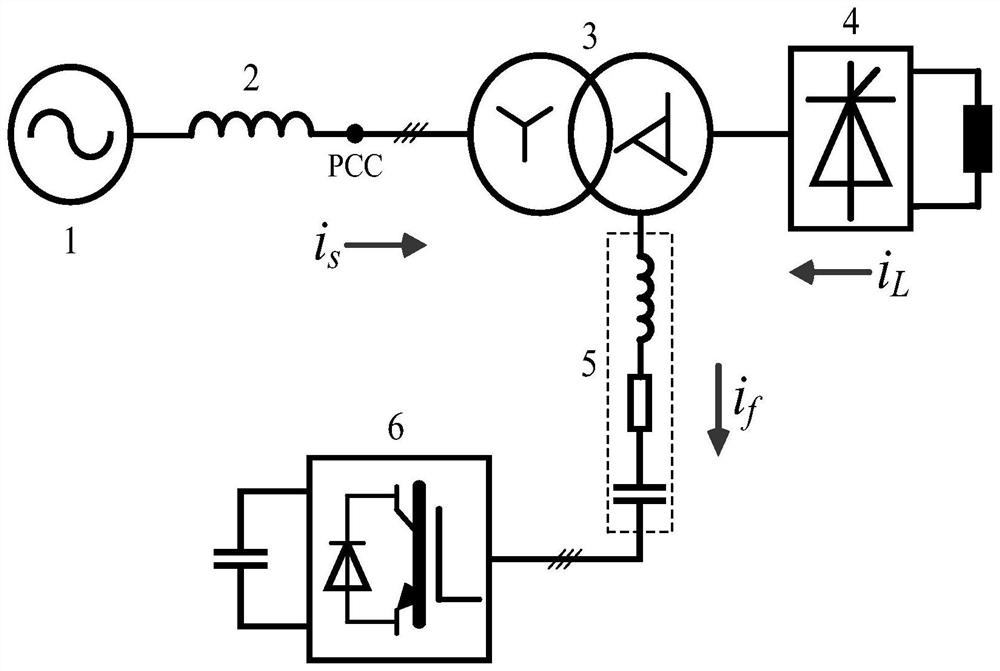
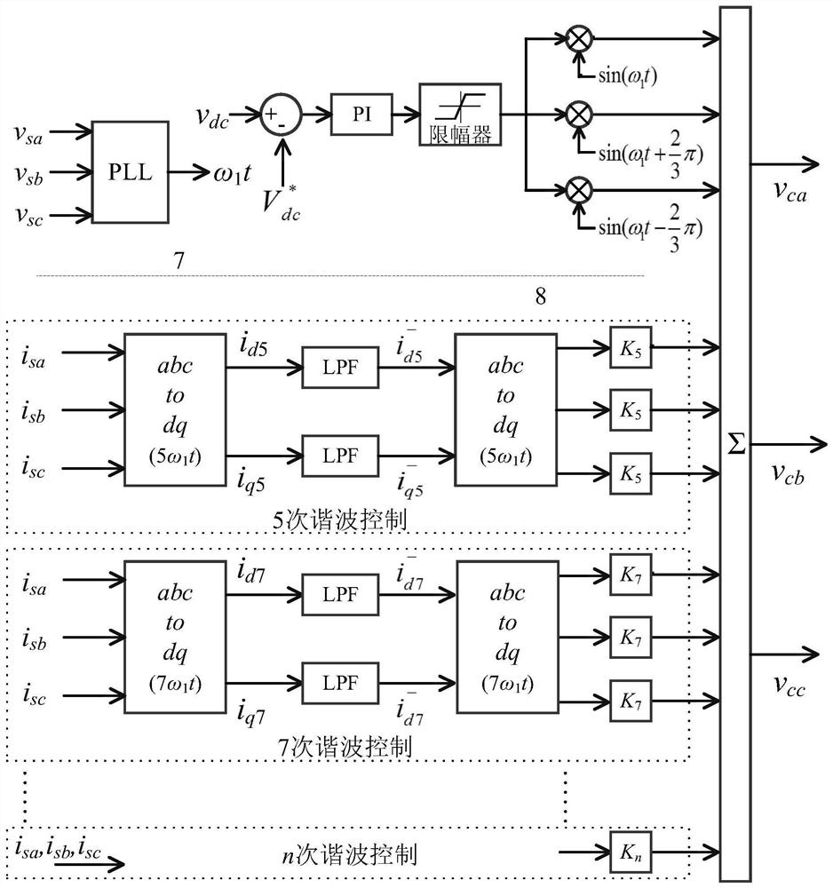
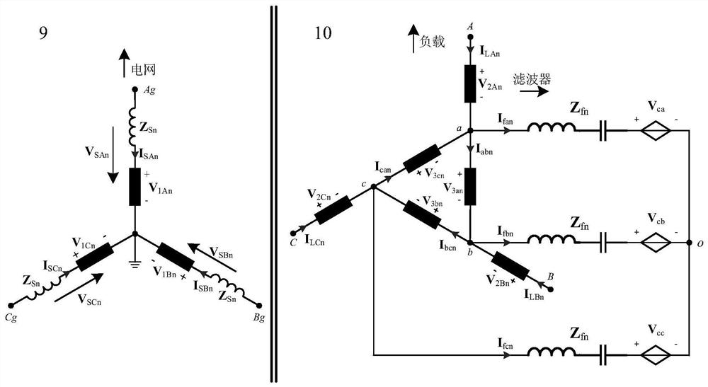
[0017] See figure 1 , a method for calculating the harmonic transfer matrix of a power induction control filter system, according to Kirchhoff's voltage-current law, multi-winding transformer voltage transfer theory, magnetic potential balance principle and virtual impedance control principle, the load harmonic as the main harmonic source is established Induction filter transformer winding current transfer matrix influenced by wave current and background harmonic v...


PUM


Abstract

The invention discloses a harmonic transfer matrix calculation method of a power induction control filtering system. The harmonic transfer matrix calculation method comprises the steps of building an induction filtering transformer winding current transfer matrix affected by a load harmonic current and background harmonic voltage which are mainly used as main harmonic sources according to a Kirchhoff voltage-current rule, a multi-winding transformer voltage transfer theory, a magnetic potential balancing principle and a virtual impedance control principle; and acquiring a quantitative calculation relation of a network-side harmonic current under two conditions that a passive filtering method and a hybrid filtering method are respectively implemented by the power induction control filtering system according to the induction filtering transformer winding current transfer matrix. The harmonic transfer matrix calculation method of the power induction control filtering system, proposed by the invention, is effective and simple and is accurate in calculation.

Description

technical field [0001] The present invention relates to a filter system, and more specifically, to a method for calculating a harmonic transfer matrix of a power induction control filter system. Background technique [0002] In the field of current rectification, active filter devices or passive filter devices are often used to improve power quality on the system grid side, while ignoring the impact of harmonic or reactive components on electrical equipment, especially on rectifier transformers. The induction filter technology redesigns the rectifier transformer, and uses an additional third filter winding to offset the harmonic flux inside the transformer, aiming to eliminate the influence of harmonics on the secondary side of the transformer. The power induction control filter system combines the advantages of induction filter technology and hybrid filter method, which greatly improves the performance of the induction filter system, so that more harmonic components can be ...

Claims


Application Information

Patent Timeline
Patent Type & Authority Patents(China)
IPC IPC(8): H02J3/01
CPCH02J3/01Y02E40/40
Inventor 刘乾易李勇胡斯佳罗隆福曹一家
Owner HUNAN UNIV
Learn More