
Intelligent wireless endoscopy camera shooting light source system

A light source system and wireless technology, applied to endoscopes, otoscopes, ophthalmoscopes, etc., can solve problems such as inability to achieve remote guidance, conferences, artificial intelligence, inability to communicate with other equipment, and expensive large-scale equipment, so as to reduce medical costs. Hidden dangers, more intuitive and more accurate viewing of lesions, small size effect

Pending Publication Date: 2017-12-12
合肥德易电子有限公司
View PDF26 Cites 2 Cited by
  • Summary
  • Abstract
  • Description
  • Claims
  • Application Information

AI Technical Summary

Problems solved by technology

[0003] 1. In grassroots medical institutions, due to the limitation of medical equipment resources and medical human resources imbalance, a doctor needs to diagnose multi-subject diseases, which will be limited by medical equipment and medical level at the same time
For large hospitals such as tertiary hospitals, they also face the problems of expensive large equipment and inconvenient movement;
[0004] 2. The transmission of minimally invasive surgery video currently requires wireless broadcast equipment or wired broadcast methods, which are complicated to install and the preparation process is cumbersome;
[0005] 3. Unable to communicate with other devices, unable to achieve the purpose of remote guidance, conferences, and artificial intelligence;
[0006] 4. The connection and light beam are cumbersome during the operation on the operating table, which brings difficulties to the doctor during operation

Method used


Image

  • Intelligent wireless endoscopy camera shooting light source system
  • Intelligent wireless endoscopy camera shooting light source system
  • Intelligent wireless endoscopy camera shooting light source system

Examples


Embodiment Construction

[0037] The technical solutions in the embodiments of the present invention are clearly and completely described below in conjunction with the accompanying drawings in the embodiments of the present invention. Obviously, the described embodiments are only part of the embodiments of the present invention, not all of them. Based on the embodiments of the present invention, all other embodiments obtained by persons of ordinary skill in the art without making creative efforts belong to the protection scope of the present invention.

[0038] In the following description, a lot of specific details are set forth in order to fully understand the present invention, but the present invention can also be implemented in other ways different from those described here, and those skilled in the art can do it without departing from the meaning of the present invention. By analogy, the present invention is therefore not limited to the specific examples disclosed below.

[0039] As shown in the ...


PUM


Abstract

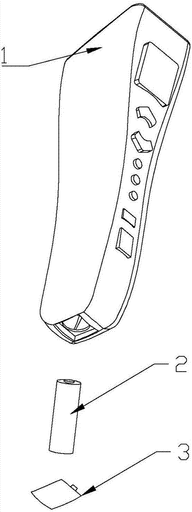
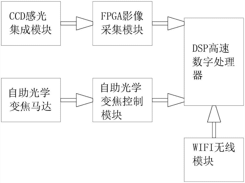
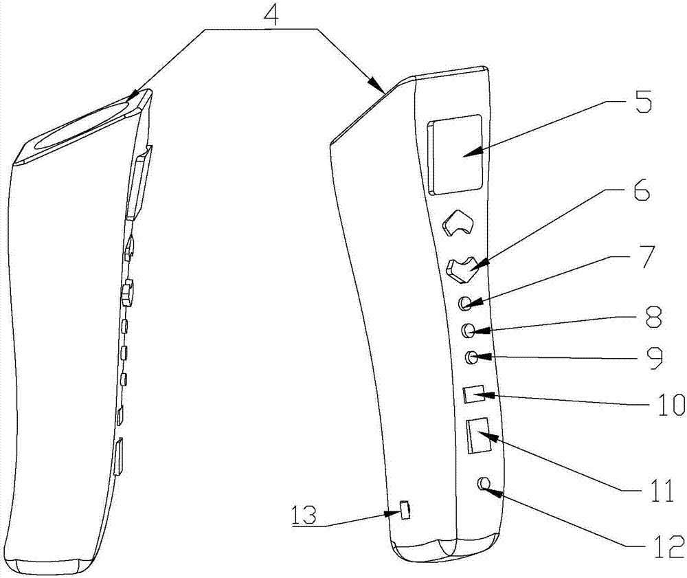
The invention discloses an intelligent wireless endoscopy camera shooting light source system, and belongs to the field of equipment for disease inspection, surgical videography and lighting in medical institutions. The system includes a functional end and a mobile terminal which is communicated with the functional end; the functional end includes a CCD photosensitive integrated module, an FPGA image acquisition module connected with CCD photosensitive integrated module, a DSP high-speed digital processor for receiving the photographic information of the FPGA image acquisition module, a self-service optical zoom control module for receiving control signals from the DSP high-speed digital processor, and a self-service optical zoom motor which is controlled by the self-service optical zoom control module and used for adjusting the optical power of the FPGA image acquisition module. The system achieves that one machine serves multiple purposes, and is compatible with the diagnosis and treatment requirements of various departments; the system can achieve synchronous videography, save video data and achieve mobile consultation, thereby achieving the purposes of remote guidance, conferences and artificial intelligence, solving the problem of tedious connection and light beams when an operation is conducted in an operating table, and facilitating the operation process.

Description

technical field [0001] The invention belongs to an intelligent wireless endoscope camera light source system used in the fields of disease inspection, operation video recording and lighting equipment in medical institutions. Background technique [0002] With the rapid development of medical equipment today, due to technical limitations, the following technical problems inevitably arise: [0003] 1. In grassroots medical institutions, due to the limitation of medical equipment resources and medical human resources imbalance, a doctor needs to diagnose multi-subject diseases, which will be limited by medical equipment and medical level at the same time. For large hospitals such as tertiary hospitals, they also face the problems of expensive large equipment and inconvenient movement; [0004] 2. The transmission of minimally invasive surgery video currently requires wireless broadcast equipment or wired broadcast methods, which are complicated to install and the preparation p...

Claims


Application Information

Patent Timeline
Patent Type & Authority Applications(China)
IPC IPC(8): A61B1/05A61B1/06A61B90/30A61B1/24A61B1/227A61B3/12
CPCA61B1/00016A61B1/051A61B1/0684A61B90/36A61B1/24A61B1/227A61B3/12
Inventor 陈飞虎张林丁帅樊松葛建军涂俊
Owner 合肥德易电子有限公司
Learn More