High-efficiency slicer

A slicer, high-efficiency technology, applied in the mechanical field, can solve the problems of slow clamping efficiency, slow replacement and cutting efficiency, etc.

Active Publication Date: 2017-12-12
浙江昊能光电股份有限公司
View PDF6 Cites 3 Cited by
  • Summary
  • Abstract
  • Description
  • Claims
  • Application Information

AI Technical Summary

Problems solved by technology

[0003] Silicon materials are mostly used in the solar energy industry and the electronics industry. In the solar energy industry, silicon pillars need to be cut and processed into sheets. The solar energy industry is developing day by day, but now many diamond wire slicers are single-wire, and the clamping efficiency is too high. Slow, such replacement and cutting efficiency is extremely slow, which can no longer meet the needs of the modern market

Method used


Image

  • High-efficiency slicer
  • High-efficiency slicer
  • High-efficiency slicer

Examples


Embodiment Construction

[0047] The following are specific embodiments of the present invention and in conjunction with the accompanying drawings, the technical solutions of the present invention are further described, but the present invention is not limited to these embodiments.

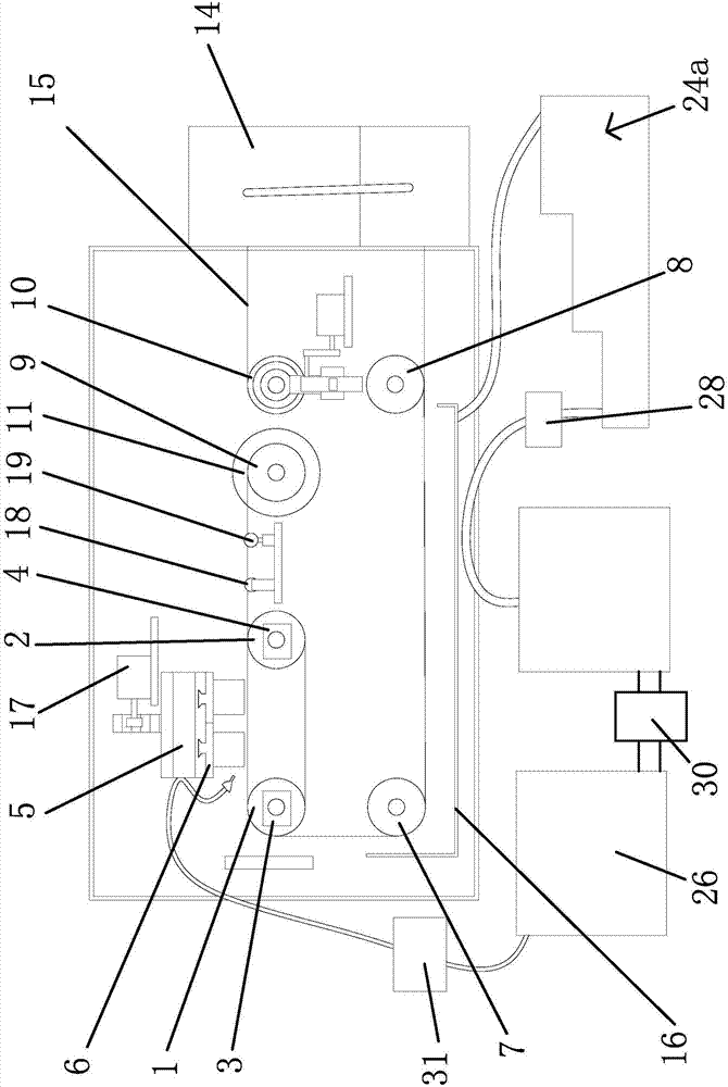
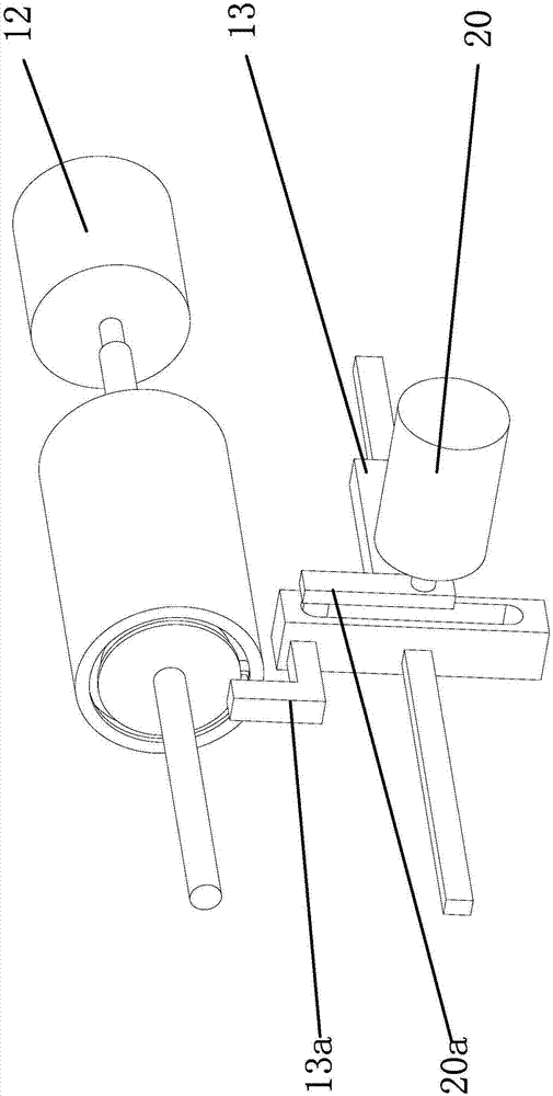
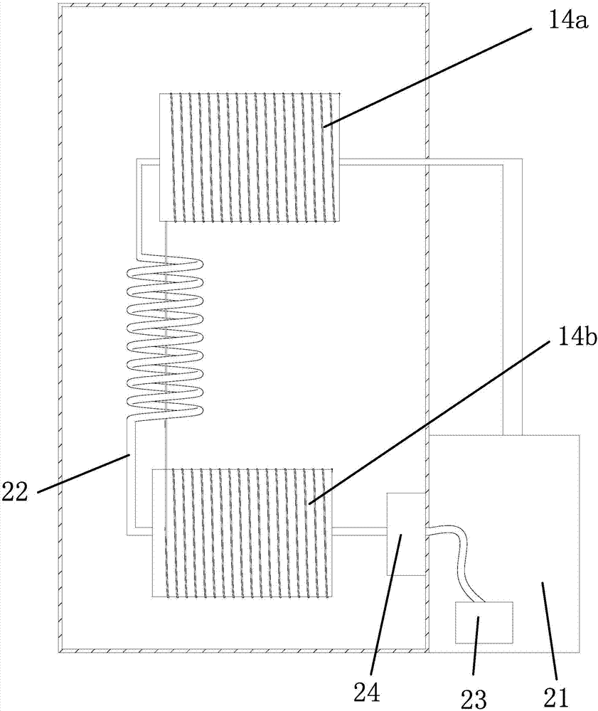
[0048] Such as Figure 1 to Figure 7As shown, a high-efficiency slicing machine includes a frame on which a wire guide wheel one 1 and a wire guide wheel two 2 are arranged, and the wire guide wheel one 1 and the wire guide wheel two 2 rotate in a circumferential direction and are axially arranged fixed on the frame by means of the method, the lead wire guide wheel 1 and the lead wire guide wheel 2 are parallel to each other, the lead wire guide wheel 1 is driven by the micro motor 1 3, the lead wire guide wheel 2 is driven by the micro motor 2 4, and the lead wire guide wheel 1 1 And the top of the lead wire guide wheel 2 is provided with a lifting platform 5, and a clamping block is fixedly provided below the lifting pla...


PUM


Abstract

The invention provides a high-efficiency slicer, and belongs to the technical field of machinery. The technical problems of too low clamping efficiency, low replacement and cutting efficiency of an existing slicer are solved. The high-efficiency slicer comprises a rack which is provided with a lead wheel I and a lead wheel II which are fixed to the rack in the form of circumferential rotation and axial arrangement and are parallel to each other, and the high-efficiency slicer is characterized in that the lead wheel I is driven by a micromotor I; the lead wheel II is driven by a micromotor II; and a lifting platform is arranged above the lead wheel I and the lead wheel II, and fixedly provided with a clamping block of which the lower part is provided with a plurality of clamping ports. The high-efficiency slicer has the advantages of quick replacement of silicon ingots and high cutting efficiency for the silicon ingots.

Description

technical field [0001] The invention belongs to the technical field of machinery, in particular to a high-efficiency slicer. Background technique [0002] The cutting principle of the diamond wire slicer is similar to that of a bow saw. The high-speed rotating and reciprocating winding drum drives the diamond wire to reciprocate. The diamond wire is tensioned by two tensioning wire wheels (spring or pneumatic), and two guide wheels are added to ensure cutting accuracy and surface shape. By automatically controlling the worktable to continuously feed towards the direction of the diamond wire console, or controlling the continuous feeding of the diamond wire console to the direction of the worktable, the grinding between the diamond wire and the object to be cut is formed to form a cut. During the cutting process, due to the small diameter and elasticity of the diamond wire, an opening angle is formed between the object to be cut and the two guide wheels on the left and right...

Claims


Application Information

Patent Timeline
Patent Type & Authority Applications(China)
IPC IPC(8): B28D5/04B28D7/00B28D7/02B28D7/04C02F9/02
CPCC02F9/00B28D5/0058B28D5/0076B28D5/0082B28D5/045C02F2301/08C02F1/281C02F1/38C02F1/001
Inventor 申炳荣
Owner 浙江昊能光电股份有限公司
Why Eureka
Try Eureka