Conveying belt forced correction device
A technology of rectification device and conveyor belt, which is applied to conveyors, conveyor objects, transportation and packaging, etc., can solve the problems that the rectification device cannot truly meet the needs of rectification, the deviation phenomenon is difficult to control, and the effect is not ideal, so as to achieve economic benefits. Considerable, eliminate the phenomenon of deviation and runaway, and eliminate the effect of hidden safety hazards
- Summary
- Abstract
- Description
- Claims
- Application Information
AI Technical Summary
Problems solved by technology
Method used
Image
Examples
Embodiment 1
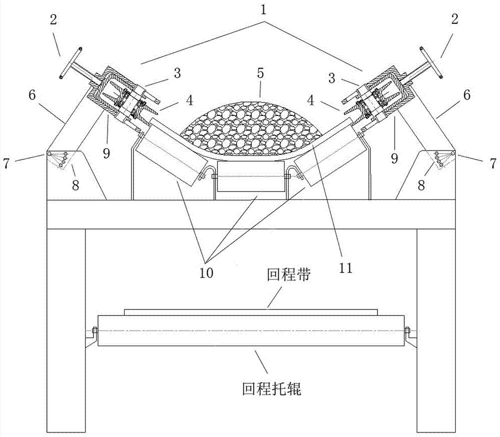
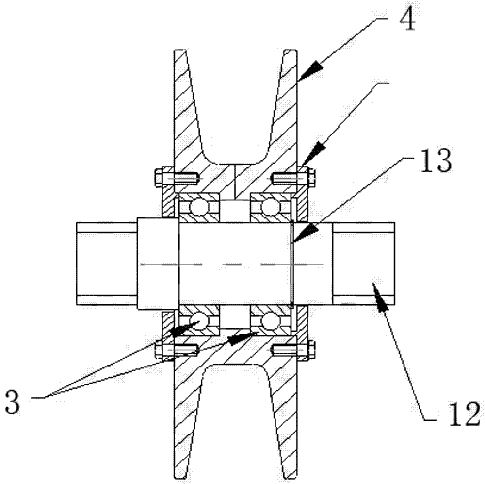
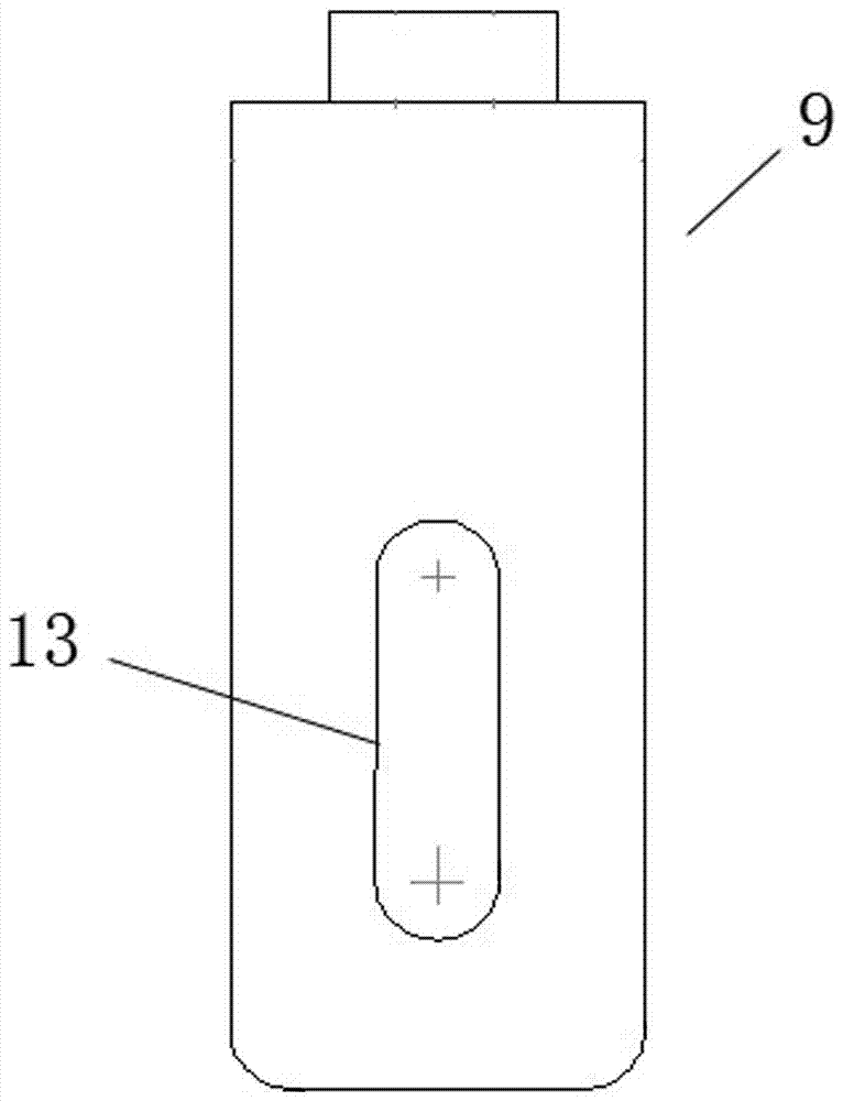
[0022] Embodiment 1: as Figure 1-4 As shown, a conveyor belt forced correction device includes an upper idler 10, an upper transmission belt 11, and guard devices on both sides of the upper idler, and the guards on both sides of the upper idler 10 are grooved pulley assemblies 1. The grooved pulley assembly 1 comprises a grooved pulley 4, a rolling bearing 3, a pulley shaft 12, a U-shaped bracket A 9, a U-shaped bracket B 14, a support arm 6, and an adjustment screw 2, and the grooved pulley 4 is installed in the shaft hole Rolling bearing 3, pulley 4, rolling bearing 3, pulley shaft 12, snap spring 13 are assembled and put into U-shaped bracket B14 and then put into U-shaped bracket A9 as a whole to form grooved pulley assembly 1. Said grooved pulley assembly 1 is supported by The arm 6 is connected to the seat body 7, the notch of the grooved pulley 4 rides on the mouth edge of the upper conveyor belt 11, but does not touch, and the symmetrical center plane of the grooved p...
Embodiment 2
[0028] Embodiment 2: as Figure 1-4 As shown, a conveyor belt forced correction device includes an upper idler 10, an upper transmission belt 11, and guard devices on both sides of the upper idler, and the guards on both sides of the upper idler 10 are grooved pulley assemblies 1. The grooved pulley assembly 1 comprises a grooved pulley 4, a rolling bearing 3, a pulley shaft 12, a U-shaped bracket A 9, a U-shaped bracket B 14, a support arm 6, and an adjustment screw 2, and the grooved pulley 4 is installed in the shaft hole The rolling bearing 3, the pulley 4, the rolling bearing 3, the pulley shaft 12, and the circlip 13 are assembled and put into the U-shaped bracket B14 and then put into the U-shaped bracket A9 as a whole to form a grooved pulley assembly 1. The grooved pulley assembly 1 is supported by Arm 6 is connected on the seat body 7, and the notch of described grooved pulley 4 rides on the mouth limit of upper conveyor belt 11, but does not touch, and the symmetric...
Embodiment 3
[0034] Embodiment 3: as Figure 1-4As shown, a conveyor belt forced correction device includes an upper idler 10, an upper transmission belt 11, and guard devices on both sides of the upper idler, and the guards on both sides of the upper idler 10 are grooved pulley assemblies 1. The grooved pulley assembly 1 comprises a grooved pulley 4, a rolling bearing 3, a pulley shaft 12, a U-shaped bracket A 9, a U-shaped bracket B 14, a support arm 6, and an adjustment screw 2, and the grooved pulley 4 is installed in the shaft hole The rolling bearing 3, the pulley 4, the rolling bearing 3, the pulley shaft 12, and the circlip 13 are assembled and put into the U-shaped bracket B14 and then put into the U-shaped bracket A9 as a whole to form a grooved pulley assembly 1. The grooved pulley assembly 1 is supported by Arm 6 is connected on the seat body 7, and the notch of described grooved pulley 4 rides on the mouth limit of upper conveyor belt 11, but does not touch, and the symmetrica...
PUM
 Abstract
Description
Claims
Application Information
 - R&D
- Intellectual Property
- Life Sciences
- Materials
- Tech Scout
- Unparalleled Data Quality
- Higher Quality Content
- 60% Fewer Hallucinations
Browse by: Latest US Patents, China's latest patents, Technical Efficacy Thesaurus, Application Domain, Technology Topic, Popular Technical Reports.
© 2025 PatSnap. All rights reserved.Legal|Privacy policy|Modern Slavery Act Transparency Statement|Sitemap|About US| Contact US: help@patsnap.com


