Glass bottle stress annealing method and system

A technology of stress annealing and glass bottles, which is applied in the direction of glass production, etc., can solve the problems of large amount of natural gas, high power consumption of blowers, and high production costs, and achieve the effects of reducing heating energy consumption, obvious energy saving effect, and sufficient annealing time

Inactive Publication Date: 2017-12-12
长兴华众玻璃有限公司
View PDF5 Cites 2 Cited by
  • Summary
  • Abstract
  • Description
  • Claims
  • Application Information

AI Technical Summary

Problems solved by technology

[0002] In the manufacturing of traditional glass bottles, from the bottle making process of the bottle making machine to the annealing process of the annealing furnace, it is an important production link, especially the annealing process of the annealing furnace has a great influence on the yield of the product; the announcement number The Chinese utility model patent CN205528423 U discloses an automatic glass bottle delivery device and an annealing furnace. The annealing furnace adopts a six-stage annealing process. Heating and heating consume a large amount of natural gas, and the blower consumes a lot of electric energy, resulting in high production costs

Method used


Image

  • Glass bottle stress annealing method and system
  • Glass bottle stress annealing method and system
  • Glass bottle stress annealing method and system

Examples


Embodiment 1

[0037] The invention discloses a stress annealing method for a glass bottle, which specifically comprises the following steps:

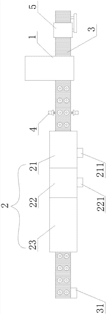
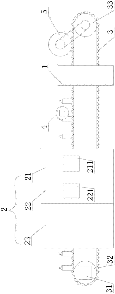
[0038] (1) Forming and conveying: the bottle making machine 1 produces glass bottles through a thermoforming process, so that the glass bottles are in a high temperature state, and the bottle making machine places the glass bottles on the conveyor belt 3;

[0039] (2) Uniform heat: transfer to the heater 4 through the conveyor belt 3, and the heater 4 carries out uniform heat treatment to the glass bottle through a high-temperature flame;

[0040] (3) Annealing: the glass bottles are transported to the annealing furnace 2 by the conveyor belt 3, heated at a high temperature in the furnace through the heating chamber 21, annealed in the furnace through the heat preservation chamber 22, and finally cooled in the cooling chamber 23.

[0041] Specifically, in the above step (2), the heating temperature of the heater 4 is T1, preferably T1 is 450° C., so ...

Embodiment 2

[0050] The difference between this embodiment and the first embodiment lies in that the number and distribution of the heaters are different.

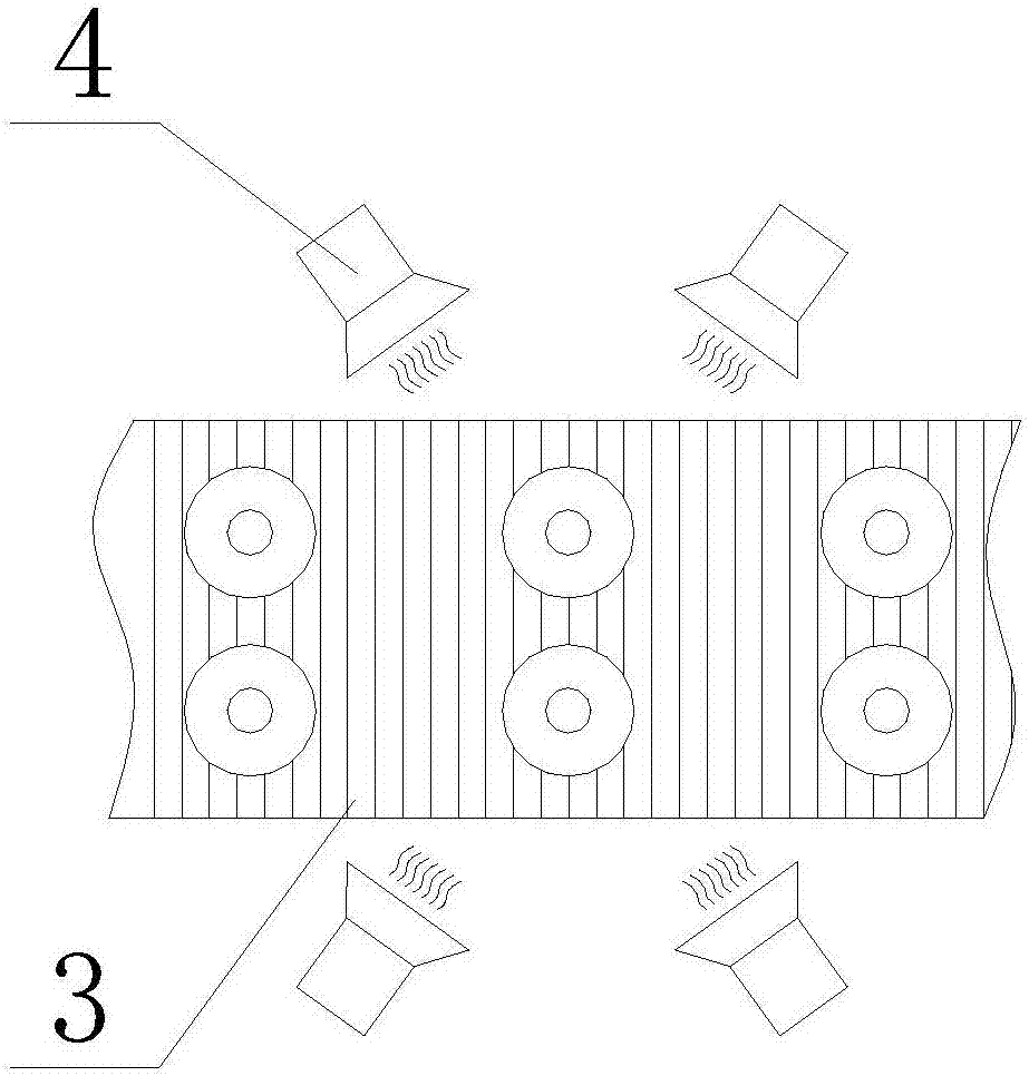
[0051] Such as image 3 As shown, in the present embodiment, there are four heaters 4, and the heaters 4 are respectively arranged on both sides of the conveyor belt 3 and arranged symmetrically. In order to gather the high-temperature flames sprayed from the flame nozzles in one place. Other structures and beneficial effects not described are the same as those in Embodiment 1.

[0052] The advantage of this setting is that the warmer conducts uniform heat treatment on the glass bottle from four angles, which can avoid uneven heating and improve the yield rate.


PUM


Abstract

The invention discloses a glass bottle stress annealing method. A bottle maker completes forming of glass bottles and conveys the glass bottles onto a conveying belt; the conveying belt conveys the glass bottles to a heating element; the heating element uniformly heat the bottle body of every glass bottle; the conveying belt conveys the glass bottles to an annealing furnace, and the glass bottles are processed through heating in a heating chamber, annealing in a heat insulating chamber and furnace cooling in a cooling chamber to complete the entire annealing process. The glass bottle stress annealing system comprises the bottle maker, the annealing furnace, the conveying belt sequentially penetrating through the bottle maker and the annealing furnace, a motor at the tail end of the conveying belt, and the heating element, wherein the heating element is arranged on the conveying belt and between the bottle maker and the annealing furnace; the annealing furnace is provided with the heating chamber for heating the glass bottles, the heat insulating chamber for annealing treatment, and the cooling chamber for furnace cooling. The glass bottle stress annealing method has the advantages of being high in yield and low in energy consumption.

Description

technical field [0001] The invention relates to the field of glass manufacturing, in particular to a stress annealing method for glass bottles and a stress annealing system for glass bottles. Background technique [0002] In the manufacturing of traditional glass bottles, from the bottle making process of the bottle making machine to the annealing process of the annealing furnace, it is an important production link, especially the annealing process of the annealing furnace has a great influence on the yield of the product; the announcement number The Chinese utility model patent CN205528423 U discloses an automatic glass bottle delivery device and an annealing furnace. The annealing furnace adopts a six-stage annealing process. The heating consumes a large amount of natural gas, and the blower consumes a lot of electric energy, resulting in high production costs. Contents of the invention [0003] In order to solve the above-mentioned shortcomings and deficiencies in the ...

Claims


Application Information

Patent Timeline
Patent Type & Authority Applications(China)
IPC IPC(8): C03B25/06
CPCY02P40/57C03B25/06
Inventor 廖冠杰陈建祖
Owner 长兴华众玻璃有限公司
Why Eureka
Try Eureka