Cleaning structure for sewing machine

A sewing machine and chip cleaning technology, which is applied to sewing machine components, sewing equipment, textiles and papermaking, etc., can solve the problems of high cost, complicated device, inconvenient installation, etc., and achieve the effect of simple structure, strong versatility, and enhanced cleaning effect

Active Publication Date: 2017-12-12
JACK SEWING MASCH CO LTD
View PDF6 Cites 17 Cited by
  • Summary
  • Abstract
  • Description
  • Claims
  • Application Information

AI Technical Summary

Problems solved by technology

[0004] The sewing machine in the above-mentioned patent documents is specially equipped with a dust suction device for dust collection, and a corresponding adsorption pump is required to form a negative pressure. The whole device is complicated, inconvenient to install, and high in cost

Method used


Image

  • Cleaning structure for sewing machine
  • Cleaning structure for sewing machine
  • Cleaning structure for sewing machine

Examples


Embodiment 1

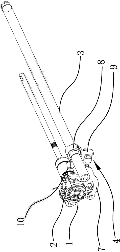
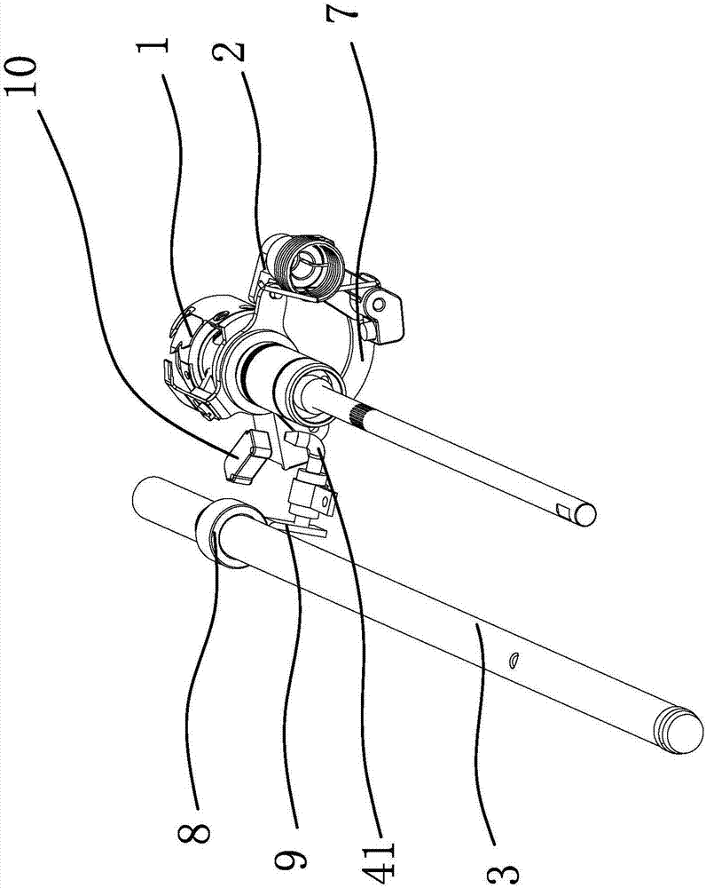
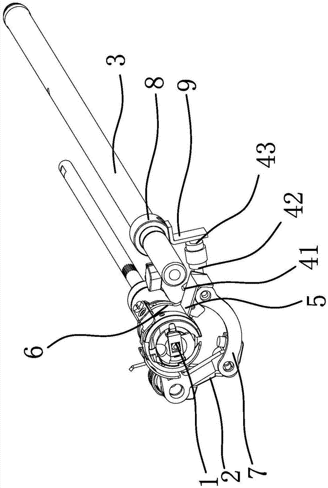
[0027] Such as Figure 1 to Figure 4 As shown, the sewing machine in this embodiment includes a rotary hook 1, a thread trimming crank 2 and a tooth lifting shaft 3, and the cleaning structure includes an air blowing assembly 4 and a chip cleaning board that can be driven by the thread trimming crank 2 or the tooth lifting shaft 3 to swing 5. The chip cleaning plate 5 is located outside the rotary hook 1; the blowing assembly 4 includes a blowing nozzle 41, a one-way valve 42 and a piston 43, the blowing nozzle 41 is located under the chip cleaning plate 5, the blowing nozzle 41 and the one-way valve 42 connected, the tooth lifting shaft 3 is connected with a drive plate 9 that can drive the piston 43 to reciprocate, and the movement of the piston 43 can supply air to the one-way valve 42; further, the sewing machine also includes a knife rest 6, and the chip cleaning plate 5 is fixed On the knife rest 6; the knife rest 6 is connected with the thread trimming crank 2 through t...

Embodiment 2

[0030]This embodiment is roughly the same as Embodiment 1, except that the sewing machine in this embodiment includes a thread-cutting cam crankshaft, a connecting rod 7 and a knife rest 6, and one end of the thread-cutting crank 2 is fixed on the thread-cutting cam crankshaft, and the other end The shaft screw is hinged with one end of the connecting rod 7, one end of the tool holder 6 is hinged at the head of the front bushing of the lower shaft, the other end of the tool holder 6 is hinged with the other end of the connecting rod 7 and the chip cleaning plate 5 is fixed on the connecting rod On this end of 7, when thread trimming is performed at the end of sewing, the crank shaft of the thread trimming cam rotates at a certain angle, driving the thread trimming crank 2 fixed on the crank shaft of the thread trimming cam, and the thread trimming crank 2 drives the connecting rod 7 to move, and the connecting rod 7 simultaneously It drives the shearing movement of the tool hol...

Embodiment 3

[0032] This embodiment is substantially the same as Embodiment 1 or Embodiment 2, the difference is that in this embodiment, a swing member is fixed on the tooth lifting shaft 3, and one side of the chip cleaning plate 5 is fixedly connected with the outer end of the swing member. When the sewing machine is working, the tooth lifting shaft 3 swings back and forth quickly at a certain angle, driving the swinging member to swing, so that the chip cleaning board 5 swings quickly, and the thread wool and oil mist adhering to the chip cleaning board 5 are thrown off under the action of inertia. To achieve the effect of cleaning waste, it also acts on the piston 43 of the air blowing assembly 4 through the drive plate 9, and combined with the check valve 42, the air blowing assembly 4 continuously blows out the airflow through the air blowing nozzle 41, and cleans the unblocked debris of the chip cleaning plate 5. Lint to further enhance the cleaning effect.


PUM


Abstract

The invention provides a cleaning structure for a sewing machine, and belongs to the technical field of sewing equipment. By the aid of the cleaning structure, the technical problems of poor effects of cleaning foreign matters at rotating shuttles of existing sewing machines and the like can be solved. The sewing machine comprises a rotating shuttle, a thread trimming crank and a feed lifting rock shaft. The cleaning structure comprises a blowing assembly and a scrap cleaning plate. The scrap cleaning plate can be driven by the thread trimming crank or the feed lifting rock shaft to swing and is positioned on the outer side of the rotating shuttle; the blowing assembly comprises a blowing nozzle, a check valve and a piston, the blowing nozzle is positioned below the scrap cleaning plate and is connected with the check valve, a driving plate capable of driving the piston to reciprocate is connected onto the feed lifting rock shaft, and air can be supplied into the check valve when the piston moves. The cleaning structure has the advantages that external air sources can be omitted, and accordingly the cleaning structure is simple and is high in universality and easy to detach and maintain; the scrap cleaning plate and the blowing assembly are combined with each other, accordingly, oil mist, lint and mixtures of the oil mist and the lint at the rotating shuttle can be cleaned, and the lint and the oil mist can be efficiently and reliably cleaned.

Description

technical field [0001] The invention belongs to the technical field of sewing equipment, and relates to a cleaning structure of a sewing machine. Background technique [0002] A sewing machine is a machine that uses one or more sewing threads to form one or more stitches on the sewing material to interweave or sew one or more layers of sewing material. Sewing machine can sew fabrics such as cotton, fiber crops, silk, wool, artificial fiber and products such as leather, plastics, paper, and the stitching that sews out is orderly and beautiful, flat and firm, and sewing speed is fast, easy to use, so it is widely used. In the current sewing machine structure, the rotary hook will throw off oil mist and thread wool at the same time when sewing, and the mixture of these oil mist and thread wool is easily adsorbed near the rotary hook on the bottom plate of the sewing machine. There is usually a sewing machine bottom thread detection device on the bottom plate behind the rotary ...

Claims


Application Information

Patent Timeline
Patent Type & Authority Applications(China)
IPC IPC(8): D05B81/00
CPCD05B81/00
Inventor 刘强许君辉潘建国
Owner JACK SEWING MASCH CO LTD
Why Eureka
Try Eureka