
Heating device with adjustable area of heat transfer surface

A heating device and heat transfer surface technology, which is applied in the field of building windows, can solve the problems that cannot be adjusted according to needs, the area of ​​the heat transfer surface is fixed, and the heating device is complicated, so as to achieve good load-bearing capacity, ensure temperature stability, and flexible use Effect

Active Publication Date: 2017-12-12
来宾市兴宾区市场监督管理局
View PDF4 Cites 2 Cited by
  • Summary
  • Abstract
  • Description
  • Claims
  • Application Information

AI Technical Summary

Problems solved by technology

However, the existing heating devices are either too complicated, or the area of ​​the heat transfer surface is fixed, and cannot be adjusted according to the needs, resulting in problems such as high cost and large heat loss.

Method used


Image

  • Heating device with adjustable area of heat transfer surface
  • Heating device with adjustable area of heat transfer surface

Examples


Embodiment

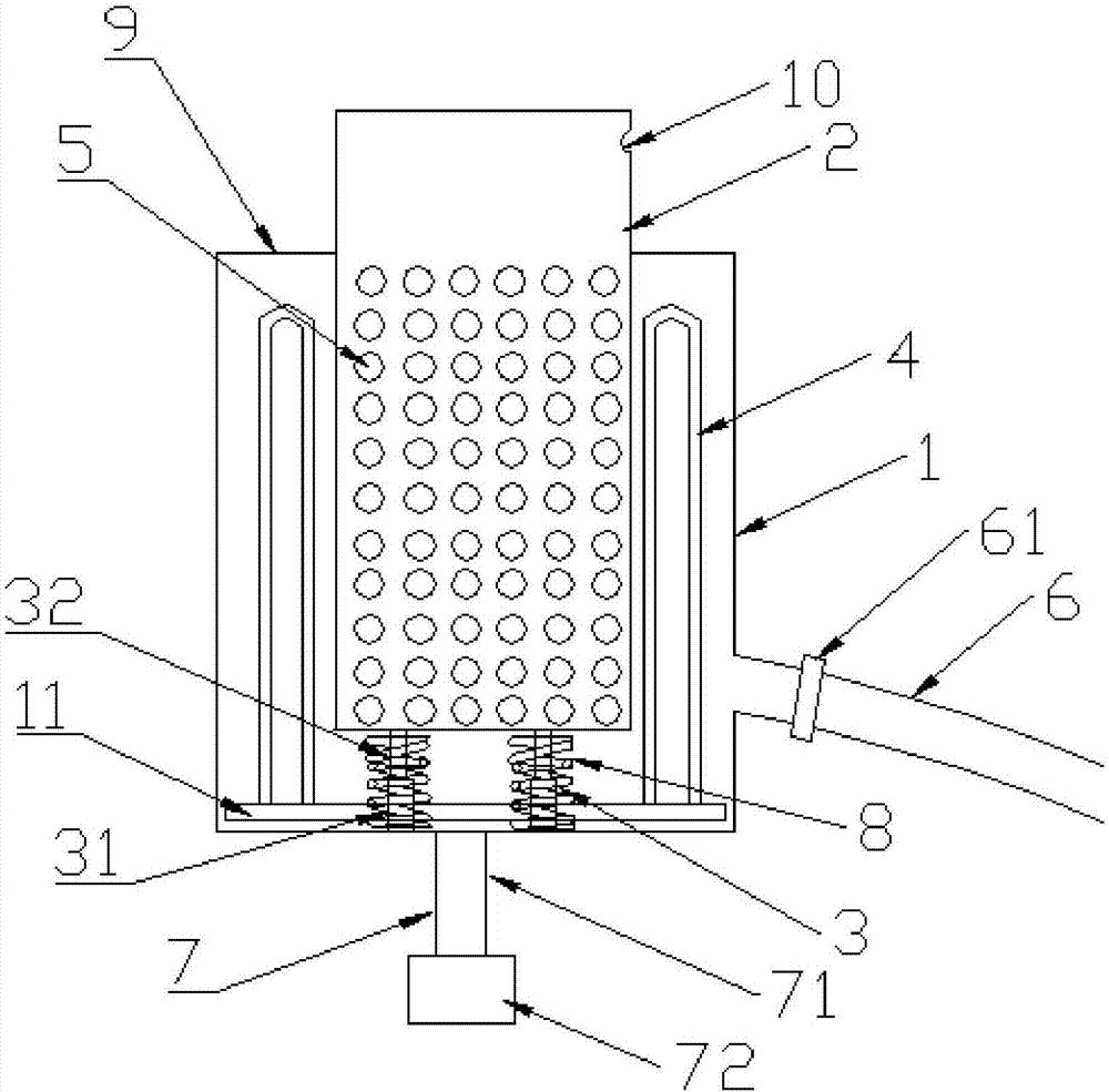
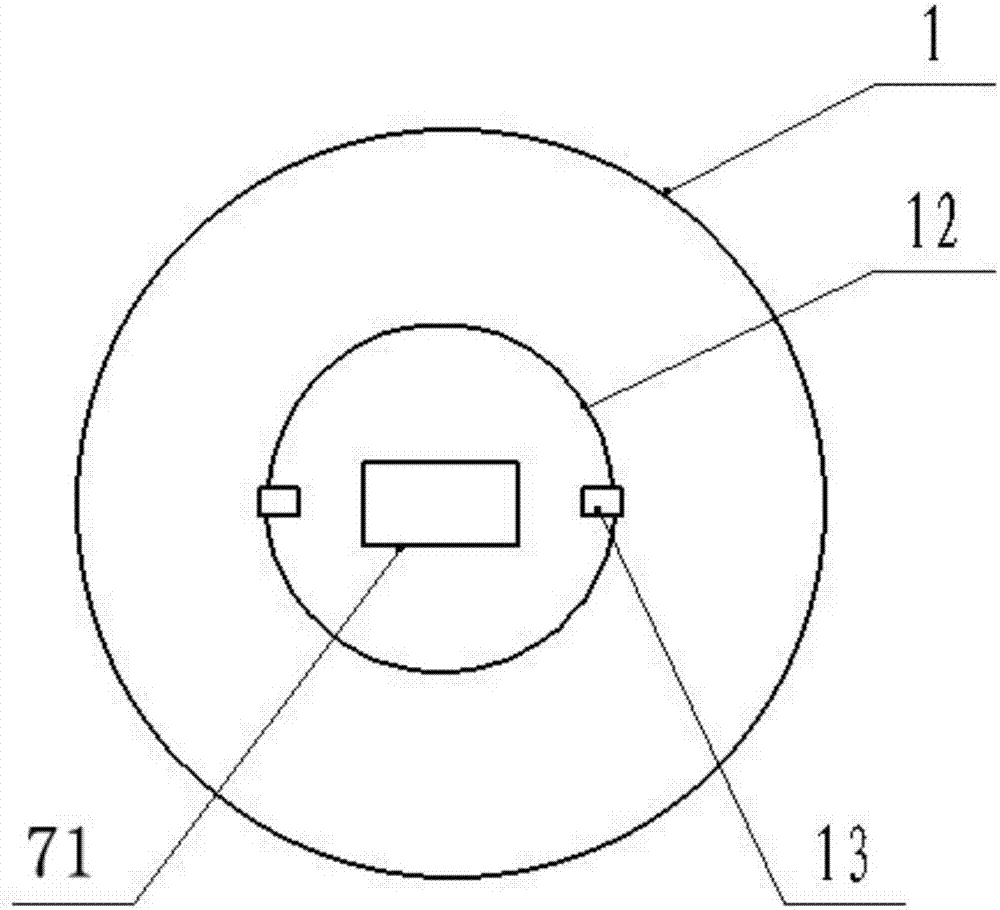
[0026] Such as figure 1 and figure 2 As shown, a heating device with an adjustable heat transfer surface area includes an outer barrel 1 and an inner barrel 2, and the inner barrel 2 is fixed in the outer barrel 1 through a telescopic rod 3. One end of the telescopic rod 3 is connected with the outer bottom of the inner barrel 2, and the other end is connected with the inner bottom of the outer barrel 1. The level of the upper end of the inner barrel 2 is higher than the level of the upper end of the outer barrel 1, and the telescopic length of the telescopic rod 3 is equal to the height of the part of the inner barrel 2 higher than the outer barrel 1. The telescopic rod 3 is also located on a movable support block 12, and is arranged at the lower end of the inner barrel 2 through the movable support block 12. In the present embodiment, the movable support block 12 is a cylinder, and the bottom of the outer barrel 1 is provided with an accommodating The round hole of the mo...

Embodiment 2

[0034] The present embodiment is the same as the embodiment 1 except that the parts by weight of the components of the insulation layer are different from the embodiment 1.

[0035] The insulation layer is mainly made of the following components by weight: 60 parts of calcium silicate powder, 30 parts of perlite, 10 parts of antimony trioxide, 10 parts of aluminum hydroxide, 20 parts of reinforcing glue, 20 parts of sodium peroxide, ten parts 2 parts of sodium dialkylsulfonate and 1 part of soluble silicone oil. Wherein, the reinforcing glue is formed by mixing silicon dioxide, wood fiber, polyvinyl alcohol and water in a weight ratio of 0.5:1.2:2.5:30.

Embodiment 3

[0037] The present embodiment is the same as the embodiment 1 except that the parts by weight of the components of the insulation layer are different from the embodiment 1.

[0038] The insulation layer is mainly made of the following components by weight: 55 parts of calcium silicate powder, 25 parts of perlite, 8 parts of antimony trioxide, 8 parts of aluminum hydroxide, 15 parts of reinforcing glue, 15 parts of sodium peroxide, ten parts 1 part of sodium dialkylsulfonate and 0.8 part of soluble silicone oil. Wherein, the reinforcing glue is formed by mixing silicon dioxide, wood fiber, polyvinyl alcohol and water in a weight ratio of 0.3:1.1:2.3:28.

[0039] The working principle of the present invention is: when the area of ​​the heat transfer surface needs to be increased, the movable support block 12 is raised by the adjustment of the lifting regulator 71 in the lifting adjustment mechanism 7, and then the telescopic rod 3 is contracted, and the inner barrel 2 is lowered...


PUM


Abstract

The invention discloses a heating device with the adjustable area of a heat transfer surface, and belongs to the technical field of heating devices. The heating device with the adjustable area of the heat transfer surface comprises an outer barrel and an inner barrel. The inner barrel is arranged in the outer barrel through telescopic rods. The level of the upper end of the inner barrel is higher than that of the upper end of the outer barrel. A heating assembly is arranged in an interlayer cavity between the outer barrel and the inner barrel. Ventilating holes are formed in the side wall, located in the outer barrel, of the inner barrel. The lower end of the side wall of the outer barrel communicates with an air inlet pipe. The telescopic rods are further arranged at the lower end of the inner barrel through a movable supporting block. A round hole is formed in the bottom of the outer barrel. Limit blocks are further arranged in the position, close to the edge of the round hole, of the outer bottom of the outer barrel. The outer bottom of the outer barrel is further connected with a lifting regulation mechanism. One end of the lifting regulation mechanism is connected with the outer bottom of the movable supporting block. According to the heating device provided by the invention, the area of the heat transfer surface of the heating device can be adjusted according to the actually required heating or drying degree, and the heating device has the characteristics of being flexible and convenient to use and the like.

Description

technical field [0001] The invention relates to the technical field of building windows, in particular to a heating device with adjustable heat transfer surface area. Background technique [0002] In production and life, it is often necessary to use a heating device to dry and heat items. Currently, there are various heating devices on the market. However, the existing heating devices are either too complicated, or the area of ​​the heat transfer surface is fixed and cannot be adjusted according to needs, resulting in problems such as high cost and large heat loss. Therefore, it is of great significance to develop an adjustable and controllable heating device. Contents of the invention [0003] The object of the present invention is to provide a heating device with adjustable heat transfer surface area. features. [0004] In order to achieve the above object, the technical scheme adopted in the present invention is: [0005] A heating device with an adjustable heat tr...

Claims


Application Information

Patent Timeline
Patent Type & Authority Applications(China)
IPC IPC(8): F26B23/00F26B23/10C04B28/18
CPCC04B28/188F26B23/00F26B23/10C04B14/18C04B14/30C04B22/06C04B22/068C04B24/16C04B24/42C04B24/2623C04B18/26
Inventor 覃永红
Owner 来宾市兴宾区市场监督管理局
Learn More