Seaborne boundary condition simulation method for FLNG device liquidation process

A technology of boundary conditions and simulation methods, applied in the field of offshore petroleum engineering, can solve problems such as time-consuming, high economic cost, and large process design margin, and achieve the effect of solving practical problems, shortening calculation time, and improving calculation reliability.

Active Publication Date: 2017-12-12
CHINA NAT OFFSHORE OIL CORP +1
View PDF3 Cites 0 Cited by
  • Summary
  • Abstract
  • Description
  • Claims
  • Application Information

AI Technical Summary

Problems solved by technology

[0003] However, in the process of designing the upper liquefaction process module of the FLNG unit, due to the special environment at sea, it is impossible to accurately describe the influence of sea conditions on the process and equipment performance during the simulation design process of the liquefaction process, and the external sloshing also affects the process dynamic simulation process. There is no efficient way to bound it
In order to meet the requirements of offshore safety, the FLNG process flow designed by the existing method has a large process design margin and a large space occupation, which leads to a high proportion of investment in the FLNG upper liquefaction process module, and the overall cost is not economical and effective.
Moreover, relying solely on experiments for data collection and analysis requires a lot of time and high economic costs.

Method used


Image

  • Seaborne boundary condition simulation method for FLNG device liquidation process
  • Seaborne boundary condition simulation method for FLNG device liquidation process
  • Seaborne boundary condition simulation method for FLNG device liquidation process

Examples


Embodiment Construction

[0034] The present invention will be described in detail below in conjunction with the accompanying drawings and embodiments.

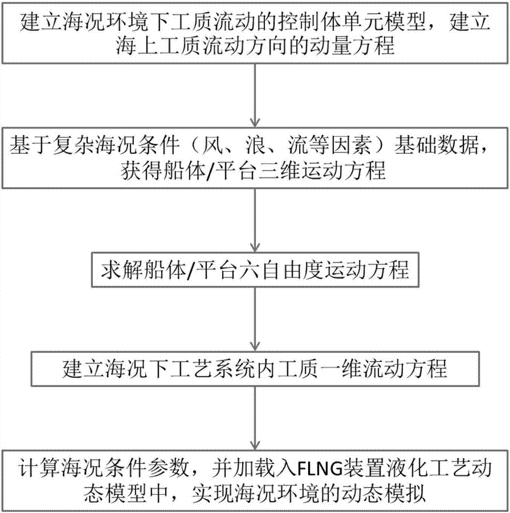
[0035] Such as figure 1 As shown, a kind of offshore boundary condition simulation method for FLNG unit liquefaction process provided by the present invention comprises the following steps:

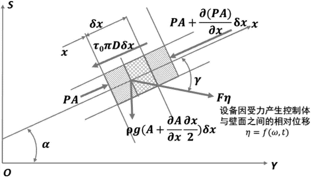
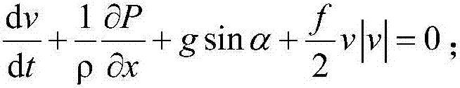
[0036] (1) Establish a three-dimensional control volume unit model for the flow of working fluid in the FLNG liquefaction process system under sea conditions, analyze the action mode of sea conditions in the process of working medium flow, and obtain the flow of working medium under the conditions of sea conditions and hull or platform motion The momentum equation for the direction;

[0037] (2) Based on the basic data of complex sea conditions in the actual operating sea area (such as wind, wave, current and other factors), obtain the three-dimensional motion of the hull or platform, and obtain the three-dimensional motion equation of the hull or platform;

[...


PUM


Abstract

The invention relates to a seaborne boundary condition simulation method for an FLNG device liquidation process. The method is characterized by comprising the following steps of: (1) establishing a three-dimensional control volume unit, working mediums of which flow in an FLNG liquidation process system, under a sea condition, and carrying out analysis to obtain a momentum equation of working medium flow directions; (2) obtaining a three-dimensional motion equation of a hull or a platform on the basis of sea condition basic data of an actual operation sea area; (3) carrying out calculation to obtain a translational motion equation and an angular motion equation of working medium gravity centers; (4) establishing a one-dimensional fluid flow equation for representing flow, in the FLNG liquidation process system, of the working mediums under the actual sea condition; and (5) calculating sea condition boundary condition parameters according to the one-dimensional fluid flow equation, and loading the sea condition boundary condition parameters into a FLNG device liquidation process dynamic model so as to realize application of actual sea condition environment to FLNG device liquidation process. The method can be widely used for improving the simulation facticity and emergency working condition prediction correctness of the FLNG device liquidation process.

Description

technical field [0001] The invention belongs to the field of offshore petroleum engineering, in particular to a method for simulating and simulating offshore boundary conditions used in the liquefaction process of an FLNG device. Background technique [0002] In the development of deep-water gas fields, due to the distance from the coast, the investment and construction of the traditional pipeline transportation mode is difficult and the risk of flow safety is high. The integration of functions such as liquefaction, storage, loading and unloading has become the first choice for the development of deep offshore gas fields and marginal gas fields. [0003] However, in the process of designing the upper liquefaction process module of the FLNG unit, due to the special environment at sea, it is impossible to accurately describe the influence of sea conditions on the process and equipment performance during the simulation design process of the liquefaction process, and the externa...

Claims


Application Information

Patent Timeline
Patent Type & Authority Applications(China)
IPC IPC(8): G06F17/50
CPCG06F30/20G06F2119/06
Inventor 李焱喻西崇王春升谢彬李玉星王清朱小松程兵韩旭亮王世圣赵晶瑞
Owner CHINA NAT OFFSHORE OIL CORP
Why Eureka
Try Eureka