Display panel

A display panel and display area technology, applied in electrical components, electrical solid devices, circuits, etc., can solve the problems of AMOLED panel chipping, chipping and other problems, so as to reduce the risk of fragmentation, prolong the service life, and improve the anti-vibration strength. Effect

Active Publication Date: 2017-12-12
EVERDISPLAY OPTRONICS (SHANGHAI) CO LTD
View PDF1 Cites 28 Cited by
  • Summary
  • Abstract
  • Description
  • Claims
  • Application Information

AI Technical Summary

Problems solved by technology

In order to improve the shock resistance of the AMOLED panel, the current practice is to install a buffer foam (Rear

Method used


Image

  • Display panel
  • Display panel
  • Display panel

Examples


Embodiment 1

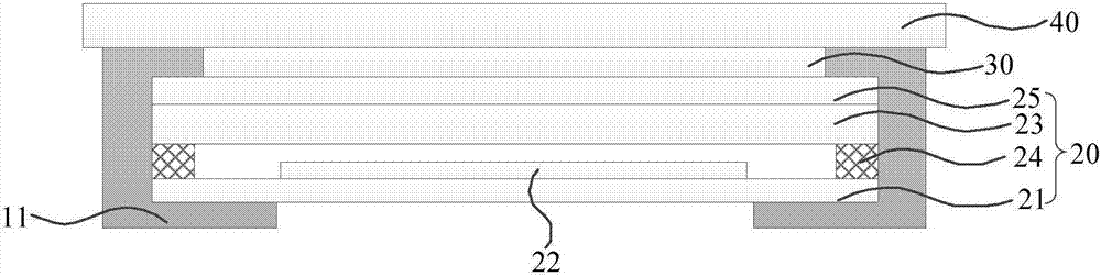
[0041] Please refer to figure 2 , the present embodiment provides a display panel, which includes: a display module 20 , a cover plate 40 , an adhesive layer 30 and a first buffer portion 11 .

[0042] The display module 20 includes an upper surface and a lower surface parallel to each other, and four sides. An organic electroluminescent display module or a liquid crystal display module may be used, and the present invention does not limit its type. This embodiment takes an organic electroluminescent display module as an example for illustration, which includes: a thin film transistor array substrate 21, a display unit 22 disposed on the thin film transistor array substrate 21, a packaging substrate 23 disposed on the display unit 22, and a The encapsulation material 24 is between the TFT array substrate 21 and the encapsulation substrate 23 and surrounds the display unit 22 , wherein the upward surface of the display module 20 along the encapsulation substrate 23 is a light-...

Embodiment 2

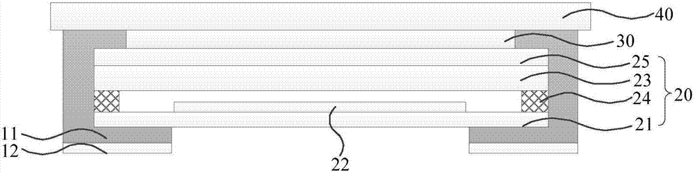
[0059] Please refer to Figure 3A , 3B and 3C, the difference between this embodiment and embodiment 1 is that the display panel further includes a second buffer portion 12 covering at least part of the first buffer portion 11 .

[0060] Existing electronic devices not only have different sizes, but also have different gaps between the display panel and the housing of the electronic device. The preset first buffer portion 11 may not be able to completely fill the gap. Part of the outer surface of the first buffer portion 11 is provided with a second buffer portion 12, which supplements and fills the gap, thereby enhancing the overall strength of the display panel and preventing the display panel from being damaged by impact when dropped.

[0061] like Figure 3A As shown, the surface of the first buffer portion 11 covered by the second buffer portion 12 is parallel to the lower surface of the display module 20, so as to fill the gap between the lower surface of the display m...

Embodiment 3

[0065] Please refer to Figure 4A , The difference between this embodiment and Embodiment 1 is that the display panel further includes a colloid 13 , and the colloid 13 is located between the first buffer portion 11 and the display module 20 . The glue 13 preferably covers at least the sides of the display module 20 , and the glue 13 may also cover part of the upper surface or part of the lower surface of the display module 20 . The side of the display module 20 is covered by the colloid 13 or together with the first buffer part 11, so that there is no gap at the edge of the display panel, and the display panel and the electronic equipment casing are integrated, effectively preventing the electronic equipment from falling or dropping. When impacting the display panel, the risk of fragmentation is reduced, and during the panel cutting process, the colloid 13 can avoid micro-cracks on the side of the display panel, reducing the risk of fragmentation.

[0066] The glue 13 filled...


PUM

PropertyMeasurementUnit
Thicknessaaaaaaaaaa
Thicknessaaaaaaaaaa

Abstract

The invention provides a display panel. The display panel comprises a display module and a cover plate and also comprises a first buffer part, wherein the display module comprises an upper surface, a lower surface and four side edges, the upper surface and the lower surface are parallel to each other, the cover plate is arranged on the upper surface of the display module by an adhesive layer, the first buffer part at least covers two of the four side edges of the display module, and the two side edges which are covered extend and cover the lower surface of the display module. The first buffer part covers a side surface and a part of the lower surface of the display module, and thus, the phenomena that the display is externally collided and edge breakage and corner breakage are generated at corners during impact can be effectively prevented; and meanwhile, in electronic equipment employing the display panel, the contact stress between an enclosure of the electronic equipment and the display panel can be adjusted by the first buffer part, the vibration strength of the display panel is improved, the breakage risk is reduced, and the service lifetime of the display panel is prolonged.

Description

technical field [0001] The present invention relates to the field of display technology, in particular to a display panel. Background technique [0002] Active matrix organic electroluminescent (AMOLED) panels are widely used due to their advantages of self-illumination, high brightness, and wide viewing angle. Glass glue (Frit glue) plays a role in isolating water vapor and oxygen in the AMOLED panel, thereby preventing water vapor, oxygen and organic materials in the AMOLED panel from chemically reacting to cause panel failure. At present, AMOLED panels are developing in the direction of thinner and narrower frames, and the width of glass glue is also becoming narrower and narrower. [0003] The AMOLED panel is vulnerable to external collisions and impacts during the handling and assembly of the whole machine, resulting in chipping and corner chipping at the edge of the AMOLED panel, thereby affecting the strength of the AMOLED panel. Please refer to figure 1 , figure ...

Claims


Application Information

Patent Timeline
IPC IPC(8): H01L27/32F16F9/30
CPCF16F9/30H10K59/00
Inventor 丁双双刘邓辉
Owner EVERDISPLAY OPTRONICS (SHANGHAI) CO LTD
Why Eureka
Try Eureka