
Continuous level to pulse circuit

A pulse circuit and level technology, applied in the direction of pulse duration/width modulation, etc., can solve the problems of using many devices, high power consumption, slow response, etc., to achieve adjustable response speed, simple structure, and no power consumption. Effect

Pending Publication Date: 2017-12-12
GUANG DONG GREENWAY TECH CO LTD
View PDF5 Cites 0 Cited by
  • Summary
  • Abstract
  • Description
  • Claims
  • Application Information

AI Technical Summary

Problems solved by technology

In the prior art, when the trigger signal width is too short or the amplitude is too low, the trigger effect cannot be achieved, so the trigger signal needs to be controlled within a certain range of time and amplitude, so as to achieve the trigger effect. At the same time, the trigger signal should be considered When the voltage of the battery pack is low, the trigger signal can still be sent. The trigger signal is only a simple function. In the past, the design circuit was more complicated, using more components, or slow response and high power consumption.

Method used


Image

  • Continuous level to pulse circuit

Examples


Embodiment Construction

[0017] In order to make the purpose, technical solutions and advantages of the embodiments of the present invention clearer, the technical solutions in the embodiments of the present invention will be clearly and completely described below in conjunction with the drawings in the embodiments of the present invention. Obviously, the described embodiments It is only some embodiments of the present invention, but not all embodiments. Based on the embodiments of the present invention, all other embodiments obtained by persons of ordinary skill in the art without making creative efforts belong to the protection scope of the present invention.

[0018] A continuous level-to-pulse circuit provided by the present invention will be described in more detail below with reference to the drawings and embodiments.

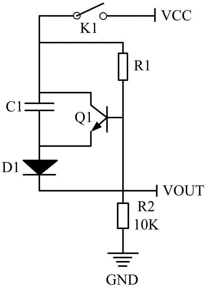
[0019] figure 1 It is a circuit diagram of an embodiment of the continuous level-to-pulse circuit of the present invention, such as figure 1 As shown, the continuous level-to-p...


PUM


Abstract

The invention discloses a continuous level to pulse circuit, comprising a power supply input end VCC, a starting switch K1 connected with the power supply input end VCC, a load resistor R1, a triode Q1 and a capacitor C1. A base of the triode Q1 is connected with the starting switch K1 through the load resistor R1. A collector is connected with the starting switch K1. The capacitor C1 is connected with the collector and an emitter of the triode Q1. One end of a diode D1 is connected with the emitter of the triode Q1, and the other end is grounded through a load resistor R2. A power supply output end VOUT is connected with the load resistor R2 in parallel. According to the circuit, a continuous level signal is imported; the continuous level signal is converted into a pulse signal; the pulse signal satisfying required amplitude and time width can be generated by flexibly changing parameters of the resistors and the capacitor; moreover, the power of the capacitor can be discharged completely and rapidly through utilization of the triode; and the circuit provided by the invention is stable and reliable and is simple in structure, and no any power is consumed basically.

Description

technical field [0001] The invention relates to the field of level-to-pulse technology, in particular to a continuous level-to-pulse circuit. Background technique [0002] Pulse signals can be used to represent information or as carriers, such as pulse code modulation (PCM) and pulse width modulation (PWM) in pulse modulation, and can also be used as clock signals for various digital circuits and high-performance chips. The pulse signal can also be used to trigger the single-chip microcomputer. When the single-chip microcomputer controlling the battery pack is powered on when the power is off, the battery pack will be activated by charging, and the signal only needs to be generated at the moment when the charger is plugged in, so the activation signal can be It is a pulse signal with a certain amplitude and width, and the single-chip microcomputer can know whether the charger is being connected by detecting the signal. In the field of battery applications, there are usually...

Claims


Application Information

Patent Timeline
Patent Type & Authority Applications(China)
IPC IPC(8): H03K7/08
CPCH03K7/08
Inventor 吴翔龙陈攀兰
Owner GUANG DONG GREENWAY TECH CO LTD
Learn More