Stamping device for LED lamp production

A technology of LED lamps and stamping devices, which is applied in the direction of forming tools, manufacturing tools, safety equipment, etc., can solve the problems of life safety hazards, low safety, and limited work efficiency of cleaning personnel, so as to protect equipment and the ground and improve safety Sexuality, the effect of improving work efficiency

Inactive Publication Date: 2017-12-15
芜湖晶鑫光电照明有限公司
View PDF6 Cites 7 Cited by
  • Summary
  • Abstract
  • Description
  • Claims
  • Application Information

AI Technical Summary

Problems solved by technology

In the production process of lamps and lanterns, it is often necessary to use stamping devices to stamp the lamp shell, etc. However, in many stamping machines, the blanking of the stamping machine is still carried out manually, which wastes manpower and material resources, and the work efficiency is limited. It is also easy to cause Safety accidents, the safety is not high, the traditional stamping machine due to the high stamping speed and high stamping pressure, such a large impact force is likely to cause damage to the equipment and the ground during work, and in the process of stamping machine work, due to the impact on the metal Stamping will produce some leftovers, usually these leftovers are cleaned manually, which is easy to pose a hazard to the life safety of the cleaning personnel, and the time required for manual cleaning will also be very long

Method used


Image

  • Stamping device for LED lamp production
  • Stamping device for LED lamp production
  • Stamping device for LED lamp production

Examples


Embodiment Construction

[0017] The following will clearly and completely describe the technical solutions in the embodiments of the present invention with reference to the accompanying drawings in the embodiments of the present invention. Obviously, the described embodiments are only some, not all, embodiments of the present invention. Based on the embodiments of the present invention, all other embodiments obtained by persons of ordinary skill in the art without making creative efforts belong to the protection scope of the present invention.

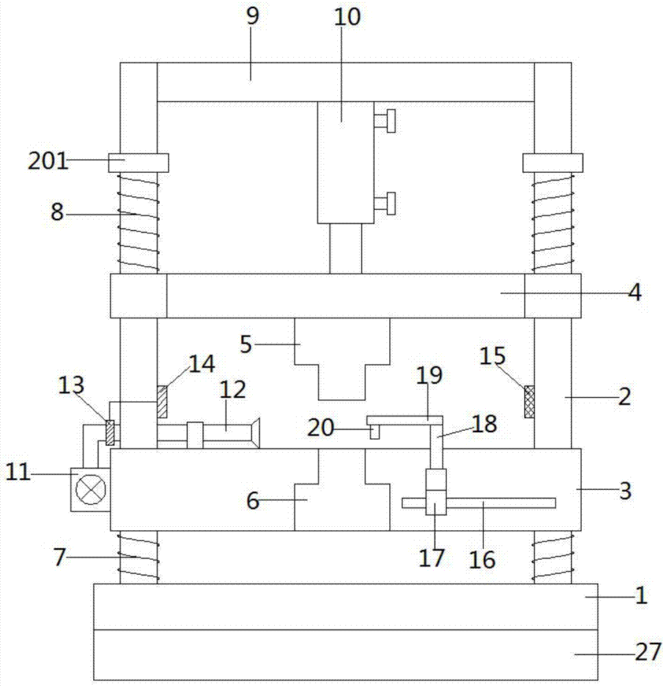
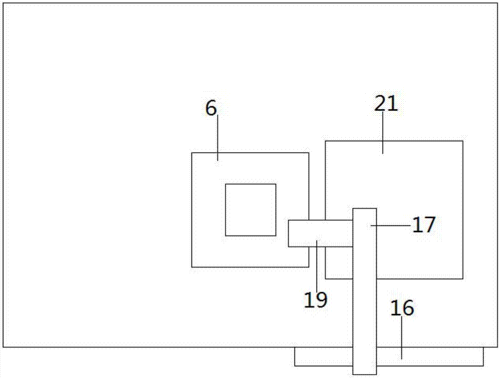
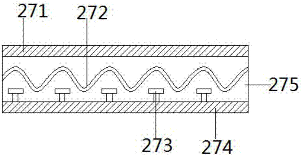
[0018] see Figure 1~3 , in an embodiment of the present invention, a stamping device for the production of LED lamps, including a support base 1, guide rods 2 arranged in parallel on the left and right ends of the upper side of the support base 1, and a lower guide rod 2 arranged between the guide rods 2 The mold support plate 3 and the upper mold support plate 4, the two sides of the lower mold support plate 3 and the upper mold support plate 4 are sleeved o...


PUM


Abstract

The invention discloses a stamping device for the production of LED lamps, which comprises a support base, guide rods arranged in parallel at the left and right ends of the upper side of the support base, a lower die support plate and an upper die support plate are arranged between the guide rods, and the lower die support plate Both sides of the support plate and the support plate of the upper mold are sleeved on the guide rod, the upper middle part of the support plate of the lower mold is provided with a lower mold, and the lower side of the support base is provided with a shock absorbing device. The shock absorbing device includes a vulcanized adhesive layer, a metal shrapnel, The stabilizer, the base and the shock-absorbing layer, the upper surface of the vulcanized adhesive layer and the bottom of the support base are vulcanized and bonded. The stamping device for the production of LED lamps of the present invention effectively protects the equipment and the ground, and can realize automatic discharge. During the process, the leftover materials produced by processing can be effectively blown away without manual operation, which improves the working efficiency and safety of the punching machine. In addition, it can effectively absorb shock and effectively improve the stability of the device.

Description

technical field [0001] The invention relates to the technical field of LED lamp production, in particular to a stamping device for LED lamp production. Background technique [0002] Luminaires refer to appliances that can transmit light, distribute and change the light distribution of the light source, including all parts required to fix and protect the light source except the light source, as well as the necessary line accessories for connection to the power supply. In the production process of lamps and lanterns, it is often necessary to use stamping devices to stamp the lamp shell, etc. However, in many stamping machines, the blanking of the stamping machine is still carried out manually, which wastes manpower and material resources, and the work efficiency is limited. It is also easy to cause Safety accidents, the safety is not high. Due to the high speed and high pressure of the traditional stamping machine, the large impact force during work is likely to cause damage t...

Claims


Application Information

Patent Timeline
Patent Type & Authority Applications(China)
IPC IPC(8): B21D22/00B21D45/04B21D37/04B21D55/00B21C51/00F16F15/06F16F15/08
CPCB21D22/00B21C51/00B21D37/04B21D45/04B21D55/00F16F15/085
Inventor 祖骅
Owner 芜湖晶鑫光电照明有限公司
Why Eureka
Try Eureka