
Plate material plane polishing structure

A plane and plate technology, applied in grinding/polishing equipment, machine tools suitable for grinding workpiece planes, grinding slides, etc., to avoid shaking, avoid machining accuracy, and reduce wear and tear

Inactive Publication Date: 2017-12-15
曾国春
View PDF0 Cites 0 Cited by
  • Summary
  • Abstract
  • Description
  • Claims
  • Application Information

AI Technical Summary

Problems solved by technology

[0003] The present invention solves the problem of difficulty in grinding different plane positions by setting a plate plane polishing structure, and improves the processing efficiency

Method used


Image

  • Plate material plane polishing structure
  • Plate material plane polishing structure
  • Plate material plane polishing structure

Examples


Embodiment 1

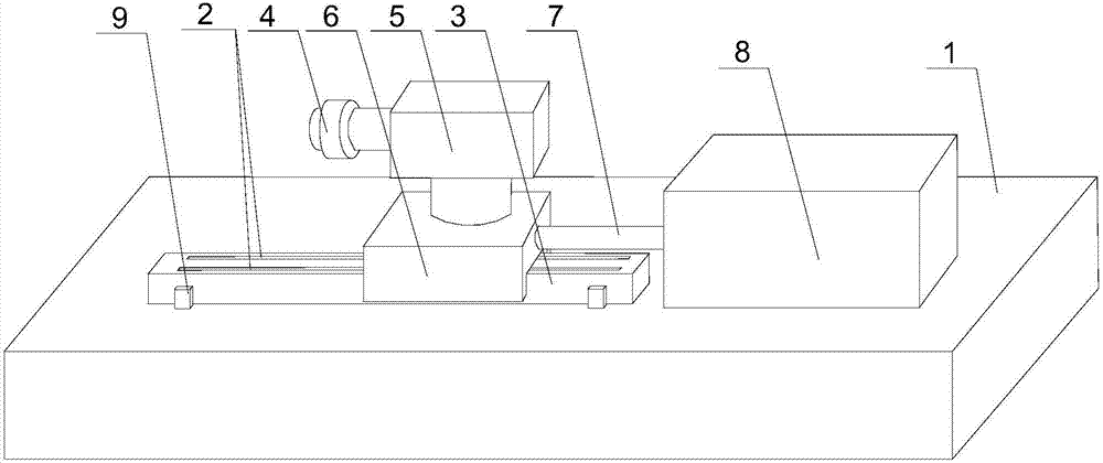
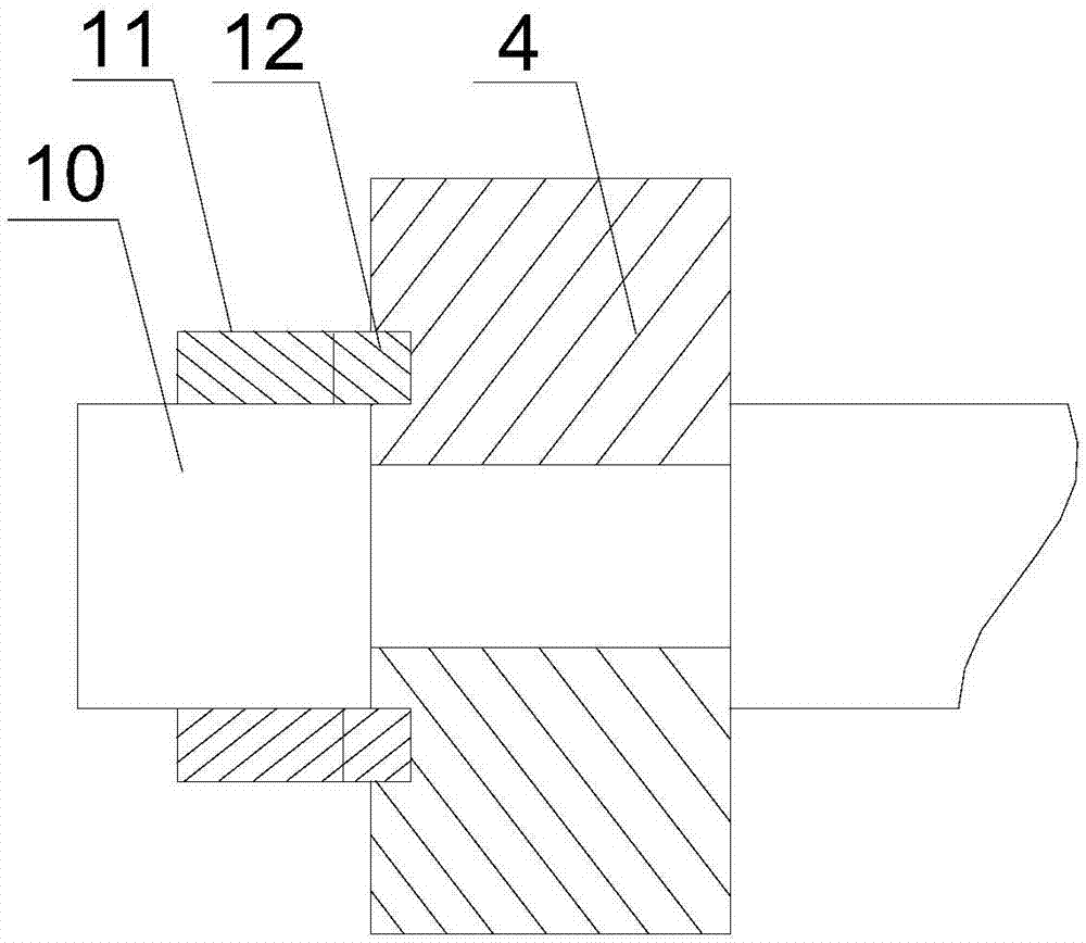
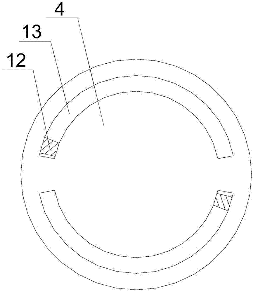
[0019] like Figure 1 ~ Figure 3 As shown, the present embodiment includes a machine tool 1, on which a guide rail 3, a cylinder 8 and a support seat 6 are arranged, a motor 5 is fixed on the support seat 6, and a grinding head 4 is provided on the output shaft of the motor 5, and a support The side wall of the seat 6 is connected with the output end of the cylinder 8 through the push rod 7, and the lower surface of the support seat 6 has a U-shaped guide groove, and the guide groove is slidably arranged on the guide rail 3, and at the two ends of the guide rail 3 A travel switch 9 is arranged on the side wall of the guide rail, and the travel switch 9 is electrically connected to the cylinder 8 through the controller. Two slide grooves 2 are opened on the upper surface of the guide rail 3, and a plurality of balls are arranged in the slide groove 2. And the ball partially protrudes from the slide groove 2 and contacts with the horizontal section of the guide groove.

[0020]...


PUM


Abstract

The invention discloses a planar polishing structure for plates, which includes a machine tool, on which a guide rail, an air cylinder and a support seat are arranged, a motor is fixed on the support seat, a grinding head is arranged on the output shaft of the motor, and the support seat is connected to the air cylinder through a push rod. There is a guide groove on the lower surface of the support seat, and the guide groove is slidably set on the guide rail. There are travel switches on the side walls at both ends of the guide rail. The travel switch is electrically connected to the cylinder through the controller. Two slide grooves are arranged on the upper surface, and a plurality of balls are arranged in the slide grooves. The U-shaped guide groove fits perfectly with the two side walls of the guide rail, which ensures the stable operation of the motor itself and the grinding head when it moves freely on the guide rail, and reduces the interaction between the motor and the guide rail, and between the grinding head and the plate. And produce the possibility of rocking, simultaneously the ball contacts with the horizontal section of guide groove, makes the sliding friction between support seat and guide rail change into rolling friction, reduces the wearing and tearing between support seat and guide rail.

Description

technical field [0001] The invention relates to the field of mechanical processing, in particular to a plate plane polishing structure. Background technique [0002] According to the process characteristics, grinding can generally be divided into: turning, milling, drilling, boring, reaming, planing, slotting, broaching, sawing, grinding, grinding, honing, superfinishing, polishing, gear machining, worm gear machining, threading, ultra-precision machining, fitter and scraping, etc. The most commonly used processes in the traditional furniture manufacturing industry are planing, sawing, grinding and polishing. In several processes of furniture manufacturing, grinding provides various components for finished assembly. Generally, the grinding structure is fixed, and most of the wood is sent to the grinding head manually or mechanically during the grinding process. The biggest defect of this processing technology is that the wood needs to move continuously to process different ...

Claims


Application Information

Patent Timeline
IPC IPC(8): B24B7/28B24B41/02B24B47/12B24B45/00
CPCB24B7/28B24B41/02B24B45/00B24B47/12
Inventor 曾国春
Owner 曾国春
Learn More