Silicon wafer drying tank

A silicon wafer and inner box technology, applied in drying, drying machine, local stirring dryer, etc., can solve the problems of high production cost, shortened life, large land occupation, etc., and achieves low cost, reduced equipment size, The effect of low power consumption

Inactive Publication Date: 2017-12-15
ZHANGJIAGANG ULTRASONIC & ELECTRIC
View PDF4 Cites 2 Cited by
  • Summary
  • Abstract
  • Description
  • Claims
  • Application Information

AI Technical Summary

Problems solved by technology

[0002] In the prior art, the silicon wafer cleaning machine is dried in a drying tunnel. This disadvantage is that it occupies a large area, consumes a lot of power, and the production cost is high, and the silicon wafer carrier such as the silicon wafer flower basket will shorten the life of the wafer under high temperature for a long time.

Method used


Image

  • Silicon wafer drying tank
  • Silicon wafer drying tank
  • Silicon wafer drying tank

Examples


Embodiment Construction

[0019] The technical solutions in the embodiments of the present invention will be described in detail below in conjunction with the accompanying drawings in the embodiments of the present invention. Obviously, the described embodiments are only some of the embodiments of the present invention, not all of them. Based on the embodiments of the present invention, all other embodiments obtained by persons of ordinary skill in the art without making creative efforts belong to the protection scope of the present invention.

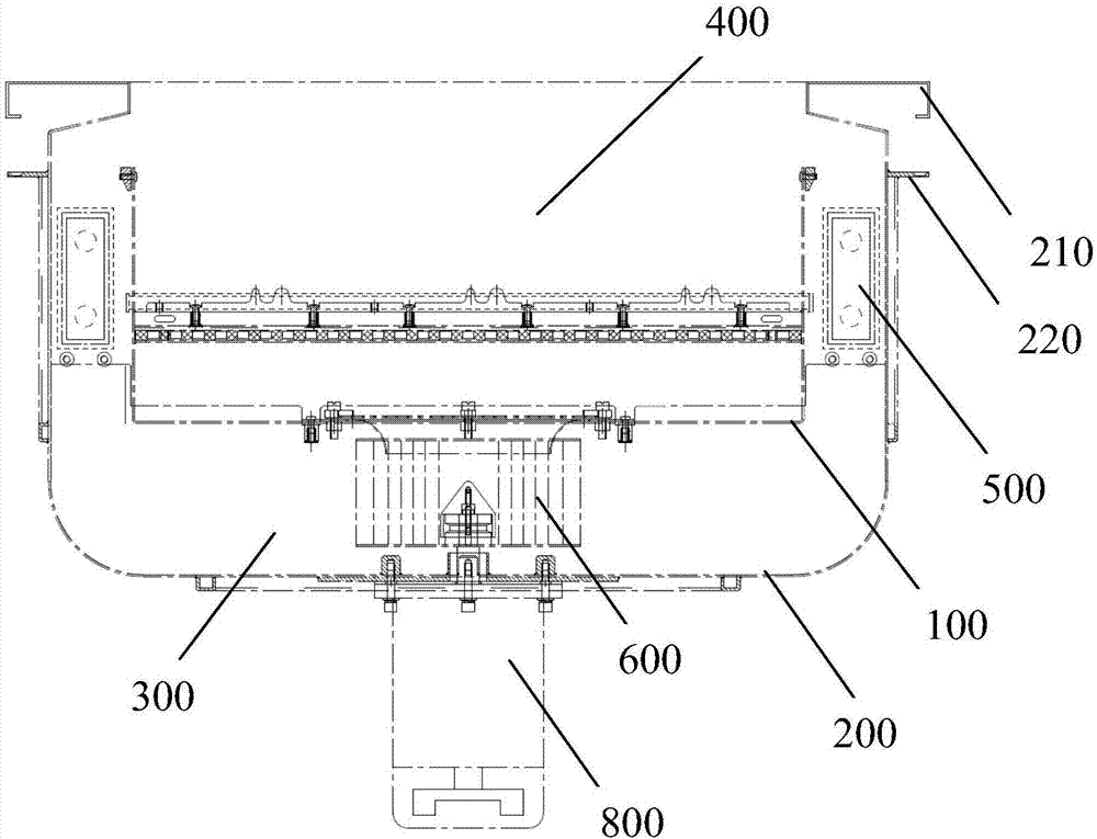
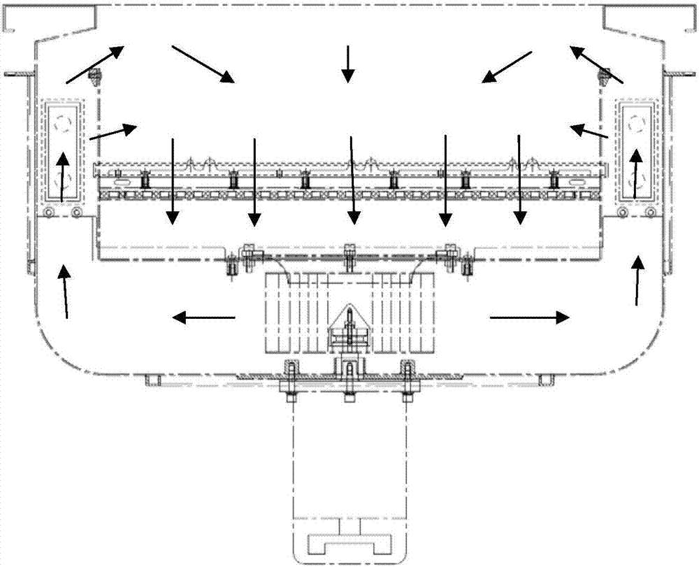
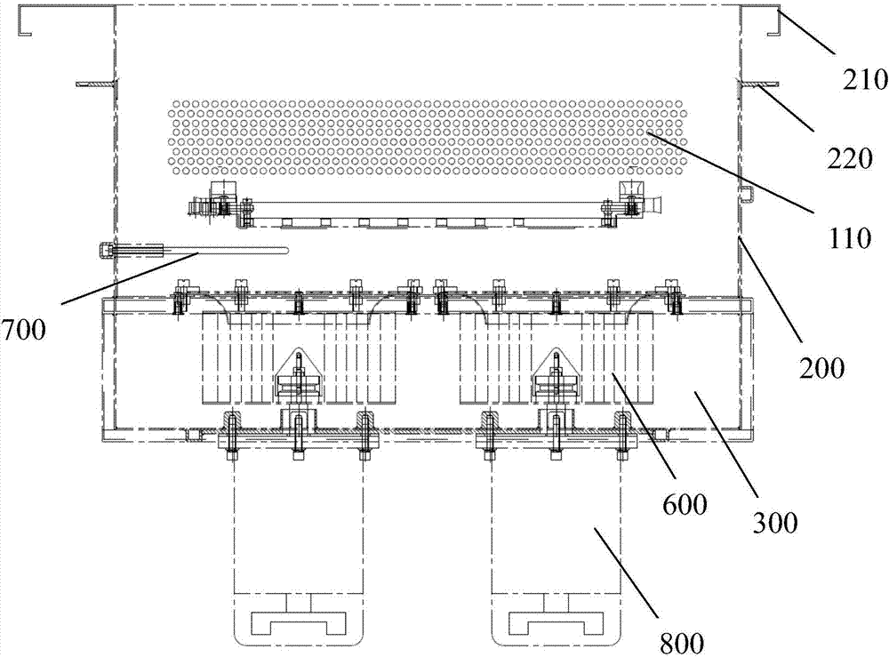
[0020] combine Figure 1-3 As shown, the silicon wafer oven includes an inner box 100 and an outer box 200. The inner box 100 is located inside the outer box 200, and a space 300 is formed between the inner box 100 and the outer box 200. The inner box Both the 100 and the outer box 200 have upward openings, and the openings are of the same size. The inner box 100 is formed with a tank 400 for containing silicon flower baskets, and at least one side of the inner...


PUM


Abstract

The invention discloses a silicon wafer drying tank. The silicon wafer drying tank comprises an inner box and an outer box; the inner box is located inside the outer box; a separating space is formed between the inner box and the outer box, and the inner box and the outer box are each provided with an upward opening, and the openings are the same in size; a tank body for containing a silicon wafer basket is formed inside the inner box, and first air holes are uniformly distributed in at least one side face of the inner box; heating pipes are installed in the separating space and right face the first air holes; second air holes are uniformly distributed in the bottom face of the inner box; and at least one centrifugal fan is installed in the separating space and is axially perpendicular to the bottom face of the inner box. The silicon wafer drying tank has the advantages that silicon wafers are dried in the tank, the equipment size is decreased, the cost is low, power consumption is also low, the power consumption of the silicon wafer drying tank is about 1/3 of that of a previous silicon wafer drying tank, and the service life of a silicon wafer carrier is prolonged.

Description

technical field [0001] The present application relates to a silicon wafer drying device, in particular to a silicon wafer drying tank. Background technique [0002] In the prior art, the silicon wafer washing machine is dried in a drying tunnel. This disadvantage is that it occupies a large area, consumes a lot of power, and the production cost is high, and the silicon wafer carrier such as the silicon wafer flower basket will shorten the life of the wafer under high temperature for a long time. . Contents of the invention [0003] The object of the present invention is to provide a silicon wafer oven to overcome the deficiencies in the prior art. [0004] To achieve the above object, the present invention provides the following technical solutions. [0005] The embodiment of the present application discloses a silicon wafer oven, which includes an inner box and an outer box, the inner box is located inside the outer box, and a space is formed between the inner box and t...

Claims


Application Information

Patent Timeline
Patent Type & Authority Applications(China)
IPC IPC(8): F26B9/06F26B21/02F26B25/08
CPCF26B9/066F26B21/02F26B25/08
Inventor 陈宏
Owner ZHANGJIAGANG ULTRASONIC & ELECTRIC
Why Eureka
Try Eureka