Vector-finite-element parallel solving simulation method based on LabVIEW and FPGA

A finite element and vector technology, applied in the field of vector finite element parallel solution simulation, can solve problems such as limited flexibility, high cost, and high energy consumption, and achieve the effect of improving speed and programming efficiency.

Active Publication Date: 2017-12-15
ZHEJIANG UNIV
View PDF3 Cites 7 Cited by
  • Summary
  • Abstract
  • Description
  • Claims
  • Application Information

AI Technical Summary

Problems solved by technology

The former is usually costly and requires a lot of energy to maintain communication between threads in a distributed computer system
The latter can effectively add parallel threads through its own multi-core processors to achieve the effect of parallel speed-up. However, since its multi-core processors are usually locked by the manufacturer when they leave the factory, the form of resource distribution is fixed by the manufacturer. Parallel operations are usually based on Among the multiple cores of the GPU, the calculation in each core is still performed in a sequential manner, and the flexibility is very limited.

Method used


Image

  • Vector-finite-element parallel solving simulation method based on LabVIEW and FPGA
  • Vector-finite-element parallel solving simulation method based on LabVIEW and FPGA
  • Vector-finite-element parallel solving simulation method based on LabVIEW and FPGA

Examples


Embodiment Construction

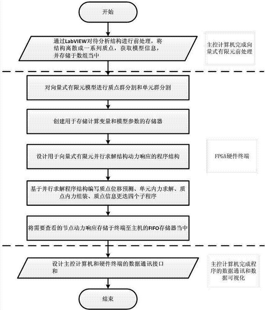
[0036]Describe the specific embodiment of the present invention in detail below in conjunction with accompanying drawing and example, wherein figure 1 It is a schematic diagram of the implementation process of the embodiment of the present invention, and its implementation steps are as follows:

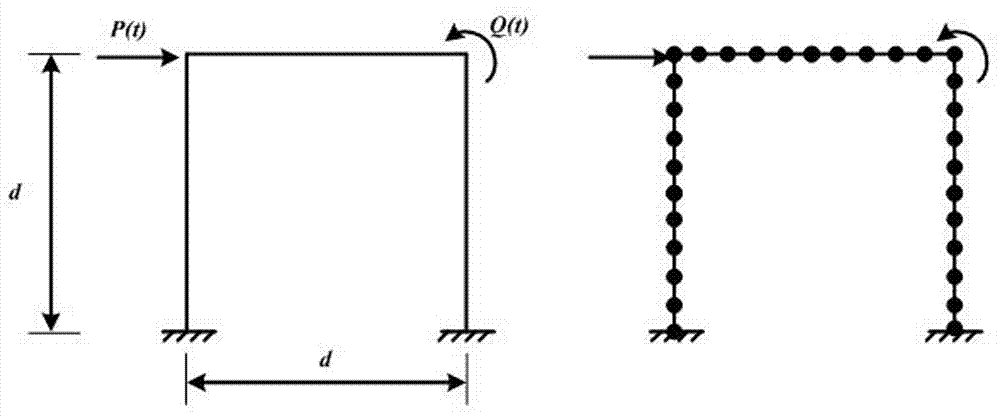
[0037] In this embodiment, the plane beam element in the vector finite element is used to calculate the rigid angle at the left end of the plane rigid frame under the concentrated load P(t)=200N horizontally to the right and the cosine periodic bending moment load Q(t) acting on the rigid angle at the right end. )=500cos(2t)N·m, the large deformation dynamic response. For detailed dimensions of the model, see figure 2 , where the cross-sectional area of ​​the beam A=0.25m 2 , the second moment of section I=5.2×10 -3 m 4 , Young's modulus E=1×10 6 N / m 2 , mass density ρ v =50kg / m 3 , the beam length d=4m; the cross-sectional area of ​​the column A=0.125m 2 , the second moment...


PUM


Abstract

The invention discloses a vector-finite-element parallel solving simulation method based on a LabVIEW and a FPGA. The method includes the steps that 1) preprocessing operation of a vector-finite-element model is carried out through the LabVIEW; 2) particle groups and unit groups of the vector-finite-element model are cut; 3) particle displacement forecasting procedures and particle information alternation procedures which correspond to the quantity of the particle groups and unit internal-force solving and particle internal-force assembling procedures which correspond to the quantity of the unit groups are written in the FPGA through the LabVIEW; 4) model particle responses needing to be viewed are stored in a FIFO storage from a terminal to a host; 5) a data communication interface between a main control computer and a FPGA hardware terminal is constructed, and data transmission between the main control computer and FPGA hardware and visualization of the FPGA-hardware calculated result are achieved. The vector-finite-element parallel solving simulation method based on the LabVIEW and the FPGA has the advantages of being high in operating speed, small in development difficulty, low in calculation cost, visual in data, capable of being packaged into a common module and the like, and is particularly suitable for analytical calculation of structural responses calculated by the vector-finite-element theory.

Description

technical field [0001] The invention relates to the field of finite element simulation in civil engineering computer aided design, in particular to a vector-type finite element parallel solution simulation method based on LabVIEW and FPGA. Background technique [0002] Vector finite element is a new structural behavior analysis method emerging in recent years. It is more efficient and convenient than traditional finite element in solving discontinuous or nonlinear mechanical behaviors such as large deformation, collision, collapse and elastoplasticity of structures. Since civil engineering structures are often complex in shape and large in size, when using vector-based finite elements for structural response analysis, the numerical model that needs to be established contains a large number of particles and elements, so the amount of calculation is extremely large. For the response analysis of complex structures, the time course response of tens of seconds in the simulation o...

Claims


Application Information

Patent Timeline
Patent Type & Authority Applications(China)
IPC IPC(8): G06F17/50
CPCG06F30/23G06F2117/08
Inventor 段元锋陶俊杰章红梅
Owner ZHEJIANG UNIV
Why Eureka
Try Eureka