Viscosity reduction stirrer on lower portion of pump

A technology of agitator and oil pump, which is applied to mixers with rotary stirring devices, chemical instruments and methods, and production of fluids, etc. Simple structure and easy processing effect

Pending Publication Date: 2017-12-19
张秀梅
View PDF7 Cites 4 Cited by
  • Summary
  • Abstract
  • Description
  • Claims
  • Application Information

AI Technical Summary

Problems solved by technology

Chinese patent 2011201089442 "Downhole Agitator" can stir the heavy oil entering the pump to improve the fluidity of the heavy oil, and can add a viscosity reducer under the pump to reduce the viscosity of the heavy oil, but it must be equipped with a hollow drive screw, hollow The length of the screw is consistent with the working stroke of the oil pump, and its length is between 4.5m and 7.3m. Its processing cost is very high and processing is very difficult, so it is difficult to implement

Method used


Image

  • Viscosity reduction stirrer on lower portion of pump
  • Viscosity reduction stirrer on lower portion of pump
  • Viscosity reduction stirrer on lower portion of pump

Examples


Embodiment Construction

[0011] Embodiments of the present invention will be described below in conjunction with the accompanying drawings.

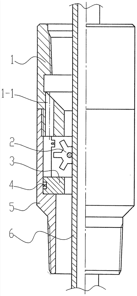
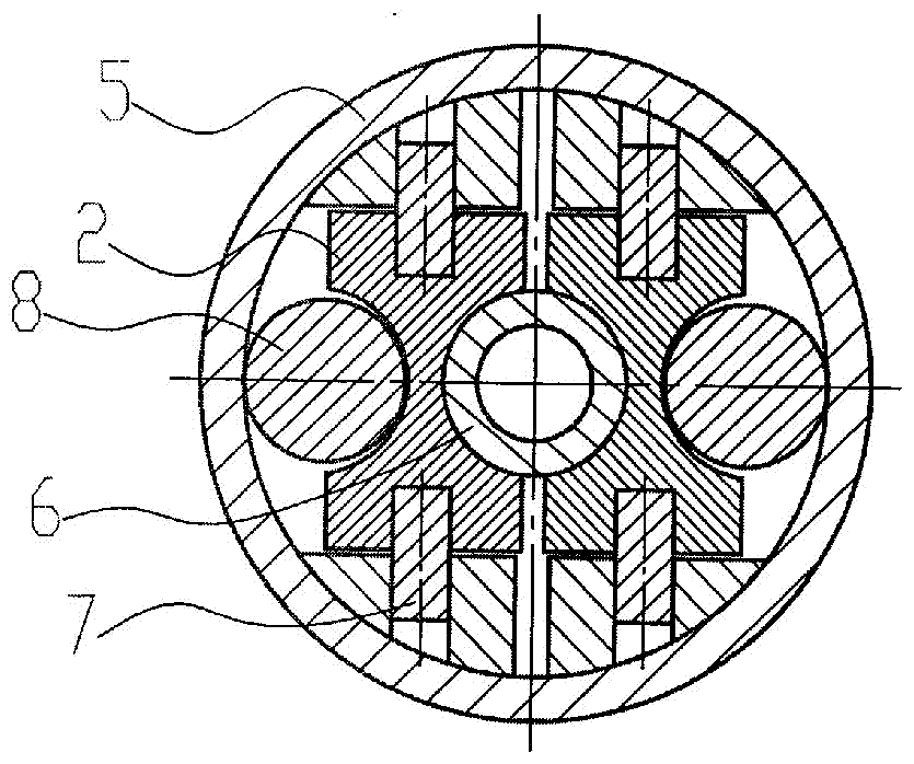
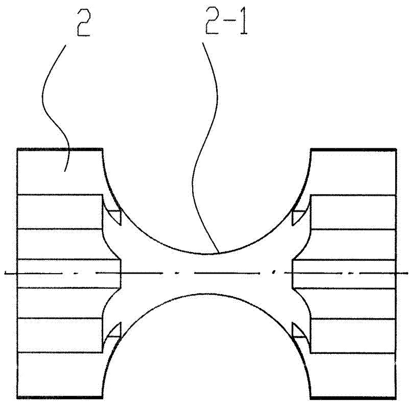
[0012] As can be seen from the figure, the embodiment of the present invention includes an upper joint 1, an impeller 2, an impeller frame 3, a hoop spring 4, a lower joint 5, a hollow rod 6, and an axle 7. Movement, horizontally drill a fixed axle hole 3-1 on the semi-cylindrical impeller frame 3, set up an impeller groove 3-2 on the semi-cylindrical impeller frame 3, and open hoop spring grooves at the upper and lower ends of the semi-cylindrical impeller frame 3 3-3, the middle of the impeller 2 is a hyperbolic cylinder 2-1, the arc radius of the hyperbolic cylinder 2-1 matches the outer wall of the hollow rod 6 (so that they can be in close contact with each other), There are blades 2-2 at both ends of the impeller 2, and a rotating shaft hole 2-3 (blind hole) is drilled on both ends of the impeller 2. The two rotating shaft holes 2-3 drilled on both ends of...


PUM


Abstract

Disclosed is a viscosity reduction stirrer on the lower portion of a pump. Fixing impeller shaft holes are transversely drilled in semicircular cylinder impeller frames, impeller grooves are formed in the semicircular cylinder impeller frames, and garter spring grooves are formed in the upper and lower ends of the semicircular cylinder impeller frames. Hyperbolic type columns are arranged in the middles of impellers. Blades are arranged at the two ends of the impellers. Rotating impeller shaft holes are drilled in the two end faces of the impellers. The impellers are placed in the impeller grooves and mounted on the impeller frames through impeller shafts inserted into the fixing impeller shaft holes and the rotating impeller shaft holes. The two impeller frames provided with the impellers are closed, a garter spring is mounted in each of the two garter spring grooves of the impeller frames, thus the impeller frames are made into a whole and then placed in the upper portion of a lower connector. The lower portion of an upper connector is connected with the upper portion of the lower connector. A hollow rod is inserted into the upper connector and penetrates through the lower connector. The inner sides of the two impellers are closely attached to the hollow rod so that the hollow rod can drive the impellers to rotate. Viscosity reduction agents injected from the hollow rod and well liquid can be stirred at the impellers when flowing upwards together, so that the viscosity reduction agents and the well liquid are uniformly mixed.

Description

technical field [0001] The invention relates to a device for mechanical oil recovery in oilfields, which is equipment for oil recovery in heavy oil wells, in particular to a pump viscosity-reducing agitator. Background technique [0002] When the heavy oil well pumps oil, the friction between the heavy oil and the sucker rod makes it difficult for the sucker rod to go down, making it impossible to pump oil normally. One of the ways to solve this kind of well pumping difficulties is to add a viscosity reducer to the casing to reduce the viscosity of the heavy oil. However, since the viscosity reducer added from the casing cannot be fully mixed with the well fluid, the added viscosity reducer does not reach the The ideal effect, the problem of difficult oil pumping still cannot be solved. The viscosity reducer swirl mixer used in the field needs to pass through the pump barrel before it can be lowered into the bottom of the pump. Since the matching pump is a special pump, it ...

Claims


Application Information

Patent Timeline
Patent Type & Authority Applications(China)
IPC IPC(8): E21B43/16B01F7/02
CPCE21B43/16B01F27/62
Inventor 高君高锐刁振雷顾鑫张雨培田荣文万明慧田荣恩张秀梅
Owner 张秀梅
Why Eureka
Try Eureka