Bubbling vaporizer

A vaporizer and bubbling technology, which is applied in combustion methods, liquid fuel supply/distribution, etc., can solve the problems of low calorific value, low operating efficiency, poor operating safety, etc., achieve pipe diameter reduction, improve operating efficiency, and operate The effect of safety improvement

Inactive Publication Date: 2017-12-19
HUALUSHENG GAS ENG NEI MONGOL
View PDF10 Cites 2 Cited by
  • Summary
  • Abstract
  • Description
  • Claims
  • Application Information

AI Technical Summary

Problems solved by technology

[0002] The bubbling carburetor is the key equipment for the production of air-mixed light hydrocarbon gas. Light hydrocarbon bubbling vaporizer, the vaporizer is a bubbling vaporizer composed of a horizontal tank, its disadvantage is that the calorific value of the air-mixed light hydrocarbon gas produced by this bubbling vaporizer is generally 4500-6000kcal / m 3 , the calorific value is low, resulting in poor operation safety and low operation efficiency of the entire air-mixed light hydrocarbon gas supply system

Method used


Image

  • Bubbling vaporizer
  • Bubbling vaporizer
  • Bubbling vaporizer

Examples


Embodiment 1

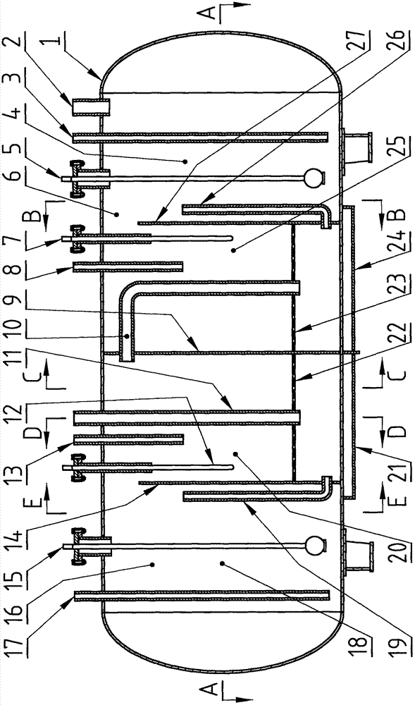
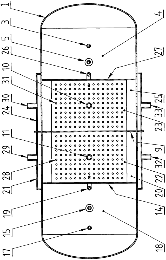
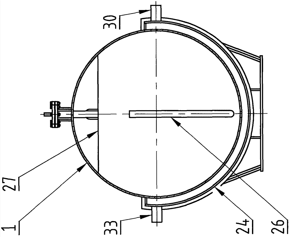
[0015] Example 1: In figure 1 , figure 2 , image 3 , Figure 4 , Figure 5 and Figure 6 Among them, a disc-shaped partition 9 made of a steel plate is welded in the cross-sectional direction of the steel horizontal tank body 1 to separate the inside of the horizontal tank body 1 into two independent closed cavities on the left and right, respectively. For the left cavity 16 and the right cavity 6, the cross-sectional direction of the horizontal tank body 1 in the left cavity 16 is welded with a disc-shaped left dividing plate 14 with a gap on the top made of a steel plate to connect the left cavity 16 The interior is divided into two cavities, respectively, the left residual liquid chamber 18 and the left vaporization chamber 20. The left residual liquid chamber 18 and the left vaporization chamber 20 are communicated through the upper gap of the disc-shaped left partition 14, and are also connected in the right cavity. The cross-sectional direction of the horizontal t...

Embodiment 2

[0017] Example 2: In figure 1 and figure 2 In the bubbling vaporizer of the present invention, the diameter of the through hole 28 on the left air disc 22 at the bottom of the left vaporization chamber 20 can also be made into 10 mm, and the number N of the through holes is still obtained according to the empirical formula obtained from the test results of the present invention. Calculation and rounding: N=19Q / R 2 , where Q and R are the design air supply volume of the bubbler vaporizer and the radius of the through hole, respectively, and the units are m 3 / h and mm, for example: the design gas supply volume of the bubbling vaporizer in the present embodiment 2 is 150 (m 3 / h), the radius of the through hole is 5mm, then the number of through holes N=(19×150) / (5×5)=114 (holes), which can be rounded to 110 holes, and the holes are arranged in the following way : along the width direction of the left air disk 22, the spacing distance is distributed in 10 rows, and each row ...


PUM


Abstract

The invention discloses a bubbling vaporizer. According to the bubbling vaporizer, a disc-shaped partition is fixedly arranged in a horizontal type tank body in the direction of the cross section of the horizontal type tank body; a disc-shaped left partition with a notch in the upper part is fixedly arranged at the left side of the disc-shaped partition so as to divide the interior of the horizontal type tank body into a left residual liquid cavity and a left vaporization cavity, and a disc-shaped right partition with a notch in the upper part is fixedly arranged at the right side of the disc-shaped partition so as to divide the interior of the horizontal type tank body into a right vaporization cavity and a right residual liquid cavity; a rectangular-thin-plate-shaped left air disc and a rectangular-thin-plate-shaped right air disc are fixedly arranged at the lower part of the left vaporization cavity and the lower part of the right vaporization cavity in the horizontal direction correspondingly; the left air disc and the right air disc are each provided with a plurality of through holes with the diameter of 5-15mm at intervals; an air pipe enters the left vaporization cavity from the outer top of the horizontal type tank body to reach the position below the left air disc at the lower part of the left vaporization cavity; and a gas phase pipe from one side of the left vaporization cavity penetrates through the disc-shaped partition from the upper part of the disc-shaped partition to enter the right vaporization cavity to reach the position below the right air disc at the lower part of the right vaporization cavity. The bubbling vaporizer has the advantages that air-light hydrocarbon mixing gas with a higher calorific value of 8000-9000kcal/m<3> can be produced.

Description

technical field [0001] The invention relates to a bubbling vaporizer, in particular to a bubbling vaporizer which uses liquid light hydrocarbons as raw materials to produce air-mixed light hydrocarbon gas. Background technique [0002] The bubbling carburetor is the key equipment for the production of air-mixed light hydrocarbon gas. Light hydrocarbon bubbling vaporizer, the vaporizer is a bubbling vaporizer composed of a horizontal tank, its disadvantage is that the calorific value of the air-mixed light hydrocarbon gas produced by this bubbling vaporizer is generally 4500-6000kcal / m 3 , the calorific value is low, resulting in poor operation safety and low operation efficiency of the entire air-mixed light hydrocarbon gas supply and use system. Contents of the invention [0003] The present invention overcomes the deficiencies in the prior art, provides a simple structure, can produce 8000~9000kcal / m 3 A bubbling evaporator with a higher calorific value mixed with ligh...

Claims


Application Information

Patent Timeline
Patent Type & Authority Applications(China)
IPC IPC(8): F23K5/22
CPCF23K5/22
Inventor 史俊和
Owner HUALUSHENG GAS ENG NEI MONGOL
Why Eureka
Try Eureka