
Wide-effect energy-saving type centrifugal pump impeller design method

A centrifugal pump impeller and design method technology, applied in calculation, instrumentation, geometric CAD, etc., can solve the problems of narrow high-efficiency area and poor adaptability of the impeller

Active Publication Date: 2017-12-19
SHANGHAI YUKE ENVIRONMENTAL ENG CO LTD
View PDF3 Cites 0 Cited by
  • Summary
  • Abstract
  • Description
  • Claims
  • Application Information

AI Technical Summary

Problems solved by technology

[0014] The impeller designed by this traditional design method has a narrow high-efficiency area and poor adaptability

Method used


Image

  • Wide-effect energy-saving type centrifugal pump impeller design method
  • Wide-effect energy-saving type centrifugal pump impeller design method

Examples


Embodiment Construction

[0045] The present invention will be further described below in conjunction with the accompanying drawings.

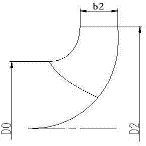
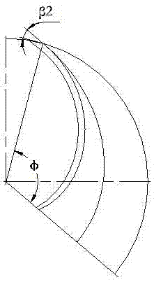
[0046] A wide-efficiency energy-saving centrifugal pump impeller design method, the outer diameter of the impeller, the equivalent inner diameter of the impeller inlet, and the width of the impeller outlet are as follows: figure 1 As shown, the blade wrap angle and blade outlet placement angle are as follows figure 2 As shown, the relationship between these geometric parameters and the performance parameters of the pump design operating point is suitable for the following relationship:

[0047] 1) Impeller outlet width b 2 Take the wider impeller outlet width, often take:

[0048] b 2 = 2.56 (ns / 100) 0.99 (2gH) 0.5 / n (m) ns<80

[0049] b 2 = 0.7 (ns / 100) 0.7 (Q / n) 1 / 3 (m) 80

[0050] b 2 = 1.6 (ns / 100) 0.99 (2gH) 0.5 / n + 0.4 (ns / 100) 0.7 (Q / n) 1 / 3 (m)ns>180

[0051] 2) The outer diameter of the impeller D 2 , for low specific speed pu...


PUM


Abstract

The invention discloses a wide-effect energy-saving type centrifugal pump impeller design method. According to the method, a new relational expression is applied between geometric parameters of impellers and performance parameters of pump design condition points, and in practical application, centrifugal pump impellers determined through the relational expression can enable centrifugal pumps to achieve the aim of being wide effect and energy-saving.

Description

technical field [0001] The invention relates to a design method of an impeller, in particular to a design method of a wide-efficiency and energy-saving centrifugal pump impeller. Background technique [0002] The centrifugal pump is not only an important equipment in the fluid delivery system, but also a large power consumer. However, the performance of centrifugal pumps in my country is seriously inefficient and wastes a lot of energy, which is completely inconsistent with the current global trend of energy conservation and emission reduction. The reasons are: 1) the design technology of the centrifugal pump itself is backward, 2) the production process and quality control are not in place, 3) the cavitation problem is ignored due to too much pursuit of high efficiency in the design point; 4) the matching between the pump and the pipeline system is poor, and the system loss Big. [0003] As the country's requirements for environmental protection and energy saving and emis...

Claims


Application Information

Patent Timeline
Patent Type & Authority Applications(China)
IPC IPC(8): G06F17/50
CPCG06F30/17
Inventor 张玉新张培富
Owner SHANGHAI YUKE ENVIRONMENTAL ENG CO LTD
Features
  • Generate Ideas
  • Intellectual Property
  • Life Sciences
  • Materials
  • Tech Scout
  • Unparalleled Data Quality
  • Higher Quality Content
  • 60% Fewer Hallucinations
Learn More